Toyota Highlander Service Manual: Vane pump ASSY (3MZ-FE)
COMPONENTS
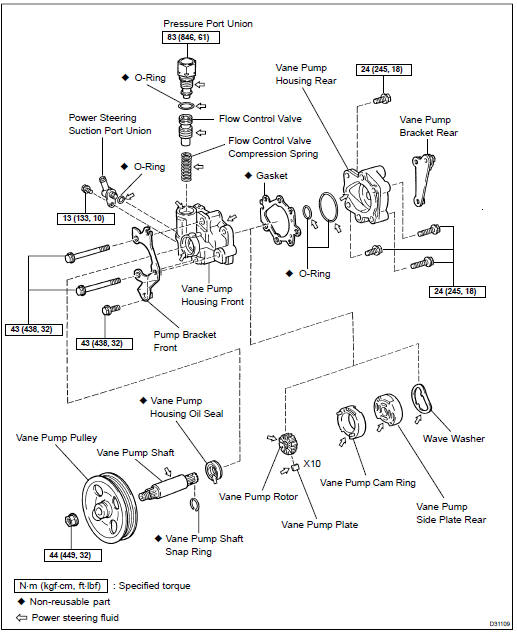
OVERHAUL
NOTICE:
- Do not overtighten when using a vise.
- When installing, coat the parts indicated by the arrows with power steering fluid (see page 51-16 ).
1. REMOVE FRONT WHEEL RH
2. DRAIN POWER STEERING FLUID
3. REMOVE FRONT FENDER APRON SEAL RH
4. DISCONNECT OIL RESERVOIR TO PUMP HOSE NO.1
(a) Remove the clip and disconnect the oil reservoir to pump hose No.1.
NOTICE: Take care not to spill fluid on the V belt.
5. REMOVE POWER STEERING OIL PRESSURE SWITCH
(a) Disconnect the connector.
(b) Remove the oil pressure switch from the union bolt.
NOTICE: Be careful not to drop the oil pressure switch.
If the oil pressure switch is dropped or severely damaged, replace it with a new one.
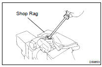
6. DISCONNECT PRESSURE FEED TUBE ASSY
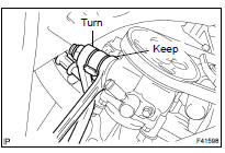
(a) Using a wrench (24 mm) to keep the pressure port union, remove the union bolt and the gasket.
(b) Disconnect the pressure feed tube assy.
7. REMOVE VANE PUMP V BELT
(a) Loosen the 2 bolts and remove the vane pump V belt.
8. REMOVE VANE PUMP ASSY
(a) Remove the 2 bolts and the vane pump assy.
9. REMOVE VANE PUMP PULLEY
(a) Using SST, keep the vane pump pulley from rotating and loosen the nut.
SST 09960-10010 (09962-01000, 09963-01000)
(b) Remove the nut and the vane pump pulley from the vane pump shaft.
10. REMOVE POWER STEERING SUCTION PORT UNION
(a) Remove the bolt and the suction port union.
(b) Remove the O-ring from the suction port union.
11. REMOVE FLOW CONTROL VALVE
(a) Remove the pressure port union.
(b) Remove the O-ring from the pressure port union.
(c) Remove the flow control valve and the compression spring.
12. REMOVE VANE PUMP BRACKET REAR
(a) Remove the 2 bolts and the vane pump bracket rear from the vane pump assy.
13. REMOVE VANE PUMP HOUSING REAR
(a) Remove the 4 bolts and the vane pump housing rear from the vane pump housing front.
(b) Remove the gasket.
(c) Remove the 2 O-rings from the vane pump housing rear.
14. REMOVE VANE PUMP SIDE PLATE REAR
(a) Remove the wave washer from the vane pump side plate rear.
HINT: Make sure direction of the part.
(b) Remove the vane pump side plate rear.
HINT: Make sure direction of the part.
15. REMOVE VANE PUMP CAM RING
HINT: Make sure direction of the part.
16. REMOVE VANE PUMP SHAFT SNAP RING
(a) Using a screwdriver, remove the vane pump shaft snap ring from the vane pump shaft.
17. REMOVE VANE PUMP ROTOR
(a) Remove the 10 vane pump plates from the vane pump rotor.
(b) Remove the vane pump rotor.
18. REMOVE VANE PUMP SHAFT
19. REMOVE PUMP BRACKET FRONT
(a) Remove the bolt and the pump bracket front from the vane pump housing front.
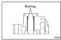
20. REMOVE VANE PUMP HOUSING OIL SEAL
(a) Using a screwdriver, remove the vane pump housing oil seal from the vane pump housing front.
NOTICE: Be careful not to damage the bushing of the vane pump housing front.
21. INSPECT VANE PUMP SHAFT AND BUSH IN HOUSING FRONT
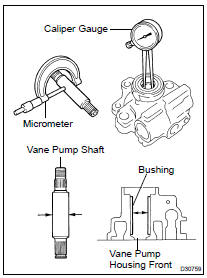
(a) Using a micrometer and a caliper gauge, measure the oil clearance.
Standard clearance: 0.027 to 0.054 mm (0.00106 to 0.00213 in.) Maximum clearance: 0.07 mm (0.0028 in.)
If clearance exceeds maximum, replace the vane pump assy.
(b) Check that there is no severe damage or wear on the bushing of the vane pump housing front and the vane pump shaft.
If necessary, replace the vane pump assy.
22. INSPECT VANE PUMP ROTOR AND VANE PUMP PLATES
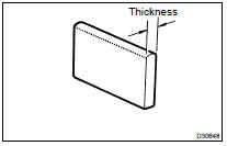
(a) Using a micrometer, measure the thickness of the vane pump plates.
Minimum thickness: 1.397 to 1.403 mm ( 0.0550 to 0.0552 in.)
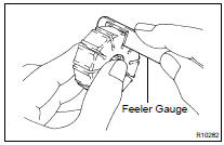
(b) Using a feeler gauge, measure the clearance between the vane pump rotor groove and the vane pump plate.
Maximum clearance: 0.03 mm (0.0012 in.)
If clearance exceeds maximum, replace the vane pump assy.
23. INSPECT FLOW CONTROL VALVE
(a) Coat the flow control valve with power steering fluid and check that it falls smoothly into the flow control valve hole under its own weight.
If it lacks smoothness, replace the vane pump assy

(b) Check the flow control valve for leakage. Close one of the holes and apply compressed air, 392 to 490 kPa (4 to 5 kgf/cm2, 57 to 71 psi), into the opposite side hole, and confirm that air does not come out from the both end holes.
If air leaks, replace the vane pump assy.
24. INSPECT FLOW CONTROL VALVE COMPRESSION SPRING
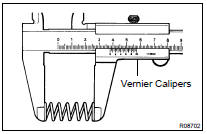
(a) Using vernier calipers, measure the free length of the compression spring.
Minimum free length: 32.24 mm (1.2693 in.)
If it is less than the minimum, replace the vane pump assy.
25. INSPECT PRESSURE PORT UNION
If the union seat in the pressure port union is severely damaged, it may cause fluid leakage. In that case, replace the vane pump assy.
26. INSTALL VANE PUMP HOUSING OIL SEAL
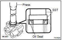
(a) Coat a new vane pump housing oil seal lip with power steering fluid.
(b) Using SST and a press, install the vane pump housing oil seal.
SST 09950-60010 (09951-00330), 09950-70010 (09951-07100)
NOTICE: Make sure that the vane pump housing oil seal is installed in the correct direction.
27. INSTALL PUMP BRACKET FRONT
(a) Install the pump bracket front with the bolt.
Torque: 43 NVm (438 kgfVcm, 32 ftVlbf)
28. INSTALL VANE PUMP SHAFT
(a) Coat bushing surface of the vane pump housing front with power steering fluid.
(b) Gradually insert the vane pump shaft from the pulley side.
NOTICE:
- Do not damage the vane pump housing oil seal lip in the vane pump housing front.
- After installation, check the vane pump housing oil seal lip.
29. INSTALL VANE PUMP CAM RING
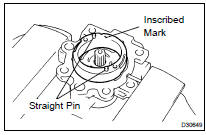
(a) Align the holes of the vane pump cam ring with the 2 straight pins, and install the vane pump cam ring with the inscribed mark facing upward.
30. INSTALL VANE PUMP ROTOR
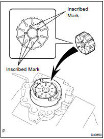
(a) Install the vane pump rotor with the inscribed mark facing downward.
NOTICE: Make sure that the vane pump rotor is installed in the correct direction.
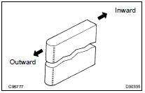
(b) Coat all 10 vane pump plates with power steering fluid.
(c) Install the vane pump plates with the round end facing outward.
NOTICE: Make sure that the vane pump plates are installed in the correct direction.
31. INSTALL VANE PUMP SHAFT SNAP RING
(a) Using a snap ring expander, install a new vane pump shaft snap ring onto the vane pump shaft.
32. INSTALL VANE PUMP SIDE PLATE REAR
(a) Align the groove of the vane pump cam ring with that of the vane pump side plate rear to install.
(b) Install the wave washer so that its protrusions fit into the slots in the vane pump side plate rear.
(c) Coat 2 new O-rings with power steering fluid and install them onto the vane pump side plate rear.
33. INSTALL VANE PUMP HOUSING REAR
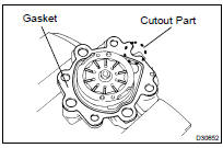
(a) Install a new gasket to the vane pump housing front.
NOTICE: Make sure that the gasket is installed with the cutout in the correct position.
(b) Install the vane pump housing rear with the 4 bolts.
Torque: 24 NVm (245 kgfVcm, 18 ftVlbf)
34. MEASURE VANE PUMP ROTATION TORQUE
(a) Check that the vane pump rotates smoothly without abnormal noise.
(b) Temporarily install the nut to the vane pump shaft.
(c) Using a torque wrench, check the vane pump rotating torque.
Rotating torque: 0.27 NVm (2.8 kgfVcm, 2.4 in.Vlbf) or less
35. INSTALL VANE PUMP BRACKET REAR
(a) Install the vane pump bracket rear with the 2 bolts.
Torque: 43 NVm (438 kgfVcm, 32 ftVlbf)
36. INSTALL FLOW CONTROL VALVE
(a) Coat the compression spring with power steering fluid and install it to the vane pump housing front.
(b) Coat the flow control valve with power steering fluid.
(c) Install the flow control valve to the vane pump housing front.
NOTICE: Make sure that the flow control valve is installed in the correct direction.
(d) Coat a new O-ring with power steering fluid and install it to the pressure port union.
(e) Install the pressure port union to the vane pump housing front.
Torque: 83 NVm (846 kgfVcm, 61 ftVlbf)
37. INSTALL POWER STEERING SUCTION PORT UNION
(a) Coat a new O-ring with power steering fluid and install it to the suction port union.
(b) Install the suction port union with the bolt to the vane pump housing front.
Torque: 13 NVm (133 kgfVcm, 10 ftVlbf)
38. INSTALL VANE PUMP PULLEY
(a) Install the vane pump pulley to the vane pump shaft.
(b) Using SST, keep the vane pump pulley from rotating and install the nut.
SST 09960-10010 (09962-01000, 09963-01000) Torque: 44 NVm (449 kgfVcm, 32 ftVlbf)
39. INSTALL VANE PUMP ASSY
(a) Temporarily install the vane pump assy with the 2 bolts.
40. INSTALL VANE PUMP V BELT
(a) Install the vane pump V belt and adjust the V belt tension (see page 14-121 ).
(b) Torque the bolt A.
Torque: 43 NVm (440 kgfVcm, 32 ftVlbf)
(c) Torque the bolt B.
Torque: 43 NVm (440 kgfVcm, 32 ftVlbf)
41. CONNECT PRESSURE FEED TUBE ASSY
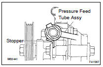
(a) Using a wrench (24 mm) to keep the pressure port union, connect the pressure feed tube assy with the union bolt and a new gasket.
Torque: 52 NVm (525 kgfVcm, 38 ftVlbf)
NOTICE: Make sure that the stopper of the pressure feed tube assy touches the pump bracket front as shown in the illustration, then tighten the union bolt.
42. INSTALL POWER STEERING OIL PRESSURE SWITCH
(a) Install the oil pressure switch to the union bolt.
Torque: 21 NVm (214 kgfVcm, 15 ftVlbf)
NOTICE: Be careful to keep oil away from the connector.
(b) Connect the connector.
43. CONNECT OIL RESERVOIR TO PUMP HOSE NO.1
(a) Connect the oil reservoir to pump hose No.1.
(b) Install the clip.
44. INSTALL FRONT FENDER APRON SEAL RH
45. INSTALL FRONT WHEEL RH
Torque: 103 NVm (1,050 kgfVcm, 76 ftVlbf)
46. BLEED POWER STEERING FLUID (SEE PAGE 51-3 )
47. INSPECT FLUID LEAK
 Vane pump ASSY (2AZ-FE)
COMPONENTS
OVERHAUL
NOTICE:
Do not overtighten when using a vise.
When installing, coat the parts indicated by the arrows with power
steering fluid
(see page 51-7 ).
1. REMOVE FRON ...
 Power steering link ASSY
COMPONENTS
OVERHAUL
NOTICE:
When installing ,coat the parts indicated by arrows with power steering fluid or
molybdenum disulfide
lithium base grease (see page 51-25 ).
1. INSPECT CENTE ...
More about Toyota Highlander:
Adjustment
1. ADJUST V (COOLER COMPRESSOR TO CRANKSHAFT PULLEY) BELT NO.1
(a) Loosen bolt A.
(b) Loosen bolt B.
(c) Apply drive belt tension by turning bolt C.
Drive belt tension:
New belt: 160 to 180 lbf
Used belt: 115 to 135 lbf
HINT:
"New V belt" refers to a belt which has been used for l ...
