Toyota Highlander Service Manual: Power steering link ASSY
COMPONENTS
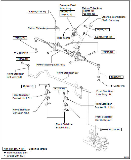

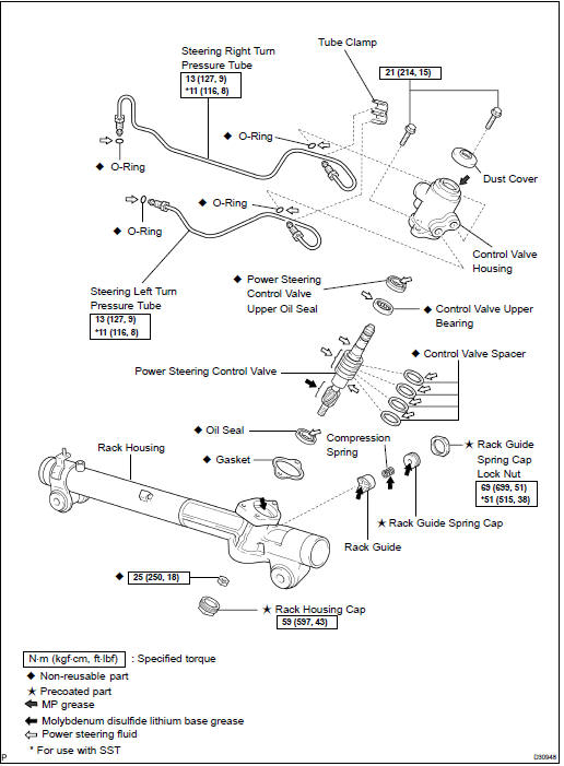
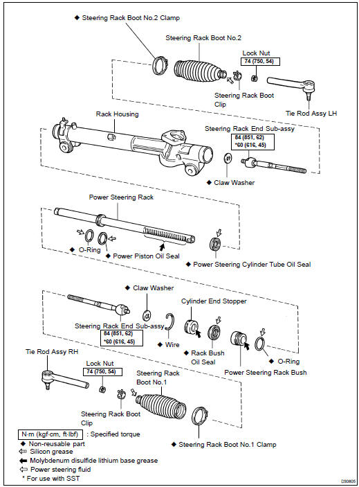
OVERHAUL
NOTICE: When installing ,coat the parts indicated by arrows with power steering fluid or molybdenum disulfide lithium base grease (see page 51-25 ).
1. INSPECT CENTER FRONT WHEEL
2. REMOVE FRONT WHEEL
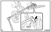
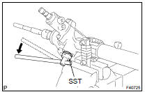
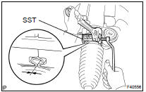
3. SEPARATE TIE ROD ASSY LH (SEE PAGE 30-21 )
SST 09628-6201 1
4. SEPARATE TIE ROD ASSY RH
SST 09628-6201 1
HINT: Perform the same procedure as for the LH.
5. SEPARATE STEERING INTERMEDIATE SHAFT SUB-ASSY
(a) Fix the steering wheel with the seat belt in order to prevent rotation.
HINT: This operation is useful to prevent damage to the spiral cable.
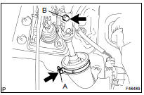
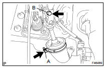
(b) Loosen bolt A and remove the clamp from the steering column hole cover No.1.
(c) Separate the steering column hole cover No.2 from the steering column hole cover No.1.
(d) Loosen bolt B.
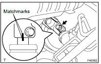
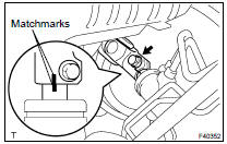
(e) Put matchmarks on the steering intermediate shaft subassy and the steering link assy.
(f) Remove the bolt and disengage the steering intermediate shaft sub-assy.
6. SEPARATE FRONT STABILIZER LINK ASSY LH (SEE PAGE 30-21 )
7. SEPARATE FRONT STABILIZER LINK ASSY RH
HINT: Perform the same procedure as for the LH.
8. REMOVE FRONT STABILIZER BRACKET NO.1 LH
(a) Remove the 2 bolts, the stabilizer bracket No.1 LH and the stabilizer bracket No.2.
(b) Remove the stabilizer bar bush No.1 from the stabilizer bar.
9. REMOVE FRONT STABILIZER BRACKET NO.1 RH
HINT: Perform the same procedure as for the LH.
10. DISCONNECT RETURN TUBE ASSY
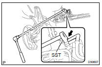
(a) Remove the tube clamp from the pressure feed tube assy.
(b) Using SST, disconnect the return tube assy from the steering link assy.
SST 09023-12701
(c) Remove the nut and the return tube clamp.
11. DISCONNECT PRESSURE FEED TUBE ASSY
(a) Using SST, disconnect the pressure feed tube assy from the steering link assy.
SST 09023-12701
(b) Remove the bolt and the pressure feed tube clamp.
12. REMOVE POWER STEERING LINK ASSY
(a) Remove the 2 bolts, the nuts and the steering link assy.
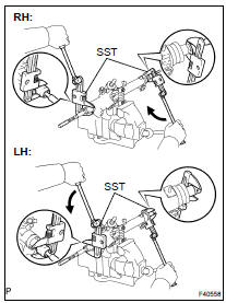
13. REMOVE STEERING LEFT TURN PRESSURE TUBE
(a) Remove the tube clamp from the turn pressure tubes.
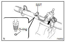
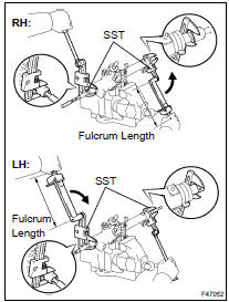
(b) Using SST, disconnect the left turn pressure tube.
SST 09023-38201
(c) Remove the 2 O-rings from the left turn pressure tube.
14. REMOVE STEERING RIGHT TURN PRESSURE TUBE
SST 09023-38201
HINT: Perform the same procedure as for the left turn pressure tube.
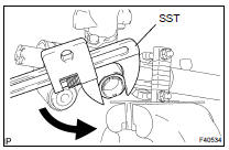
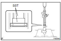
15. FIX POWER STEERING LINK ASSY
(a) Using SST, secure the steering link assy.
SST 09612-00012
HINT: Wrap the SST with tape before use, in order to prevent damaging the steering link assy.
16. REMOVE TIE ROD ASSY LH
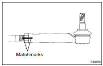
(a) Put matchmarks on the tie rod assy LH and the rack end.
(b) Loosen the lock nut and remove the tie rod assy LH and the lock nut.
17. REMOVE TIE ROD ASSY RH
HINT: Perform the same procedure as for the LH.
18. REMOVE STEERING RACK BOOT CLIP
(a) Remove the 2 boot clips.
19. REMOVE STEERING RACK BOOT NO.2 CLAMP
(a) Using pliers, remove the rack boot No.2 clamp.
NOTICE: Be careful not to damage the boot.
20. REMOVE STEERING RACK BOOT NO.1 CLAMP
HINT: Perform the same procedure as for the No.2 clamp.
NOTICE: Be careful not to damage the boot.
21. REMOVE STEERING RACK BOOT NO.2
22. REMOVE STEERING RACK BOOT NO.1
23. REMOVE STEERING RACK END SUB-ASSY
(a) Using a screwdriver and a hammer, unstake the claw washer.
NOTICE: Avoid any impact to the steering rack.
(b) Using 2 SST, remove the rack end RH and the claw washer.
SST 09922-10010
NOTICE: Use SST 09922-10010, following the direction shown in the illustration.
(c) Using 2 SST, hold the steering rack and remove the rack end LH and the claw washer.
ST 09922-10010
NOTICE: Use SST 09922-10010, following the direction shown in the illustration.
24. REMOVE RACK GUIDE
(a) Using SST, remove the spring cap lock nut.
SST 09922-10010
NOTICE: Use SST 09922-10010, following the direction shown in the illustration.
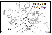
(b) Using SST, remove the rack guide spring cap.
SST 09631-10021
(c) Remove the compression spring and the rack guide.
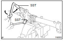
25. REMOVE POWER STEERING CONTROL VALVE
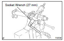
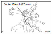
(a) Using a socket wrench (27 mm), remove the rack housing cap.

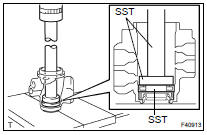
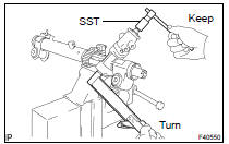
(b) Using SST, keep the control valve shaft and remove the nut.
SST 09616-0001 1
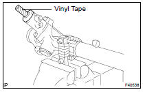
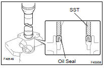
(c) Wrap vinyl tape around the spline of the control valve in order to prevent damaging the oil seal.
(d) Remove the dust cover from the control valve housing
(e) Remove the 2 bolts and the control valve housing with the control valve.
(f) Remove the gasket.
(g) Using a plastic hammer, remove the control valve.
(h) Remove the oil seal from the control valve.
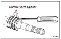
(i) Using a screwdriver, remove the 4 control valve spacers.
NOTICE: Be careful not to damage the spacer grooves.
26. REMOVE POWER STEERING CONTROL VALVE UPPER OIL SEAL
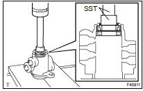
(a) Using SST and a press, remove the control valve upper bearing and the upper oil seal from the control valve housing.
SST 09950- 70010 (09951- 07150), 09950- 60010 (09951-00250)
27. REMOVE CYLINDER END STOPPER
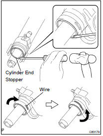
(a) Using a screwdriver and a hammer, turn the cylinder end stopper clockwise until the wire end is visible through the service hole.
(b) Using a screwdriver and a hammer, turn the cylinder end stopper counterclockwise, and remove the wire and the cylinder end stopper.
28. REMOVE POWER STEERING RACK
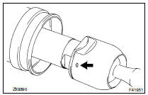
29. REMOVE POWER STEERING RACK BUSH
(a) Remove the rack bush with the rack bush oil seal from the power steering rack.
(b) Using SST, remove the rack bush oil seal from the rack bush.
SST 09527-2101 1, 09612-24014 (09613-22011)
NOTICE: Be careful not to drop the rack bush.
(c) Using a screwdriver, remove the O-ring from the rack bush.
30. INSPECT POWER STEERING RACK
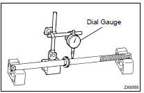
(a) Using a dial gauge, check for runout of the steering rack and teeth wear.
Maximum runout: 0.3 mm (0.0118 in.)
NOTICE: Make sure that the steering rack is placed holizontally.
(b) Check the rack surface for wear and damage.
If runout exceeds maximum, replace the power steering link assy.
31. REMOVE POWER STEERING CYLINDER TUBE OIL SEAL
(a) Using SST and a press, remove the cylinder tube oil seal.
SST 09950- 70010 (09951- 07360), 09950- 60010 (09951-00290)
NOTICE: Be careful not to damage the inside surface of the rack housing.
32. REMOVE POWER PISTON OIL SEAL
(a) Using a screwdriver, remove the oil seal and the O-ring.
NOTICE: Be careful not to damage the oil seal groove.
33. INSTALL POWER PISTON OIL SEAL
(a) Coat a new O-ring with power steering fluid and install it to the steering rack.
(b) Expand the new oil seal with your fingers.
NOTICE: Be careful not to overly expand the oil seal.
(c) Coat the oil seal with power steering fluid.
(d) Install the oil seal to the steering rack, and adjust with your fingers.
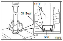
34. INSTALL POWER STEERING CYLINDER TUBE OIL SEAL
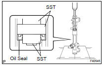
(a) Coat a new oil seal lip with power steering fluid.
(b) Using SST and a press, install the oil seal.
SST 09950- 60010 (09951- 00450, 09951- 00250, 09952-06010), 09950-70010 (09951-07360)
NOTICE: Make sure that the oil seal is installed in the correct direction.
35. INSPECT TIE ROD ASSY LH
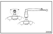
(a) Secure the tie rod assy LH in a vise.
(b) Install the nut to the stud bolt.
(c) Flip the ball joint stud back and forth 5 times.
(d) Using a torx) wrench, turn the nut continuously at a rate of 2 to 4 seconds per turn and take the torque reading on the 5th turn.
Turning torque: 0.49 to 3.43 NVm (5.0 to 35.0 kgfVcm, 4.3 to 30.4 in.Vlbf) If not within the specified torque, replace the tie rod assy LH.
36. INSPECT TIE ROD ASSY RH
HINT: Perform the same procedure as for the LH.
37. INSTALL POWER STEERING RACK
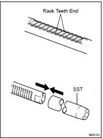
(a) Apply grease to the rack teeth ends.
(b) Affix SST to the steering rack.
SST 09631-33010
HINT: If necessary, scrape the burrs off the rack teeth ends and burnish.
(c) Coat SST with power steering fluid.
(d) Install the steering rack to the rack housing.
(e) Remove SST.
38. INSTALL POWER STEERING RACK BUSH
(a) Coat a new rack bush oil seal lip with power steering fluid.
(b) Using SST and a press, install the rack bush oil seal to the rack bush.
SST 09950- 60010 (09951- 00400), 09950- 70010 (09951-07100)
NOTICE: Make sure that the oil seal is installed in the correct direction.
(c) Coat a new O-ring with power steering fluid and install it to the rack bush.
(d) Coat the rack bush oil seal lip with power steering fluid.
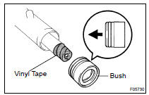
(e) Install the rack bush to the rack housing.
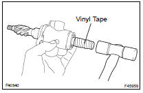
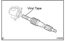
HINT: Wrap vinyl tape around the end of the steering rack in order to prevent damaging the rack bush oil seal.
39. INSTALL CYLINDER END STOPPER
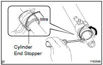
(a) Align the installation hole for the wire of the cylinder end stopper with the slot of the rack housing.
(b) Install a new wire into the cylinder end stopper.
(c) Using a screwdriver, turn the cylinder end stopper counterclockwise by 450 50 .
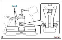
40. AIR TIGHTNESS TEST
(a) Install SST to the rack housing.
SST 09631-12071 (09633-00010)
(b) Apply a vacuum of 53 kPa (398 mmHg, 15.65 in.Hg) for about 30 seconds.
(c) Check that there is no change in the vacuum pressure.
If there is a change in the vacuum pressure, check the installation of the oil seals.
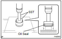
41. INSTALL POWER STEERING CONTROL VALVE UPPER OIL SEAL
(a) Coat the control valve upper bearing with grease, and a new control valve upper oil seal lip with power steering fluid.
(b) Using SST and a press, install a new control valve upper oil seal.
SST 09950- 70010 (09951- 07150), 09950- 60010 (09951-00180, 09952-06010, 09951-00320)
NOTICE: Make sure that the oil seal is installed in the correct direction.
(c) Using SST and a press, install the control valve upper bearing.
SST 09950- 70010 (09951- 07150), 09950- 60010 (09951-00180, 09952-06010, 09951-00340)
42. INSTALL POWER STEERING CONTROL VALVE
(a) Expand 4 new valve spacers with your fingers.
NOTICE: Be careful not to overly expand the valve spacers.
(b) Coat the 4 valve spacers with power steering fluid.
(c) Install the 4 valve spacers to the control valve, and adjust with your fingers.
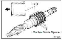
(d) Carefully slide the tapered end of SST over the valve spacers until they fit to the control valve.
SST 09631-20081
NOTICE: Be careful not to damage the valve spacers.
(e) Coat the oil seal lip with power steering fluid.
(f) Install the control valve into the valve housing.
NOTICE: Be careful not to damage the valve spacer and oil seal lip.
HINT: Wrap vinyl tape around the end of the steering rack in order to prevent damaging the oil seal.
(g) Coat a new oil seal lip with power steering fluid.
(h) Using SST and a press, install the oil seal.
SST 09612-2201 1
NOTICE: Make sure that the oil seal is installed in the correct direction.
(i) Apply grease to the needle roller bearing of the rack housing and the serrated part of the control valve.
(j) Install a new gasket to the valve housing.
(k) Install the control valve housing with the control valve to the rack housing with the 2 bolts.
Torque: 21 NVm (214 kgfVcm, 15 ftVlbf)
HINT: Wrap vinyl tape around the lower spline of the control valve in order to prevent damaging the oil seal.
(l) Using SST, keep the control valve from rotating and install a new lock nut.
SST 09616-0001 1
Torque: 25 NVm (250 kgfVcm, 18 ftVlbf)
(m) Apply sealant to 2 or 3 threads of the rack housing cap.
Sealant: Part No. 08833-00080, THREE BOND 1344, LOCTITE 242 or equivalent
(n) Using a socket wrench (27 mm), install the rack housing cap.
Torque: 59 NVm (597 kgfVcm, 43 ftVlbf)
(o) Using a punch and a hammer, stake the rack housing cap and the rack housing.
43. INSTALL RACK GUIDE
(a) Apply grease to the compression spring and the contact surface of the rack guide.
(b) Install the rack guide and the compression spring.
(c) Apply sealant to 2 or 3 threads of the rack guide spring cap.
Sealant: Part No. 08833-00080, THREE BOND 1344, LOCTITE 242 or equivalent
(d) Temporarily install the rack guide spring cap.
44. ADJUST TOTAL PRELOAD
(a) Temporarily install the RH and LH rack ends sub-assy, in order to prevent the oil seal from being damaged by the rack teeth.
(b) Using SST, torque the rack guide spring cap.
SST 09631-10021
Torque: 25 NVm (250 kgfVcm, 18 ftVlbf)
(c) Using SST, loosen the rack guide spring cap.
SST 09631-10021
(d) Using SST, turn the control valve to right and left 1 or 2 times.
SST 09616-0001 1
(e) Using SST, loosen the rack guide spring cap until the compression spring stops functioning.
SST 09631-10021
(f) Using SST and a torque wrench, tighten the rack guide spring cap until the preload falls within specifications.
SST 09616-0001 1, 09631-10021
Preload (turning): 1.2 to 1.5 NVm (12.2 to 15.3 kgfVcm, 10.6 to 13.3 in.Vlbf)
(g) Apply sealant to 2 or 3 threads of the rack guide spring cap lock nut.
Sealant: Part No. 08833-00080, THREE BOND 1344, LOCTITE 242 or equivalent
(h) Temporarily install the rack guide spring cap lock nut.
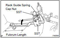
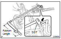
(i) Using SST, hold the rack guide spring cap and using another SST, torque the spring cap lock nut.
SST 09616-0001 1, 09922-10010
Torque: 51 NVm (515 kgfVcm, 38 ftVlbf)
NOTICE: Use SST 09922-10010, following the direction shown in the illustration.
HINT: Use a torque wrench with a fulcrum length of 345 mm (13.58 in.).
(j) Precheck the total preload.
Preload (turning): 1.2 to 1.5 NVm (12.2 to 15.3 kgfVcm, 10.6 to 13.3 in.Vlbf)
(k) Remove the RH and LH rack ends sub-assy.
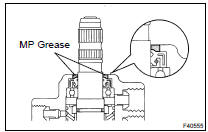
(l) Apply MP grease around the control valve shaft, as shown in the illustration.
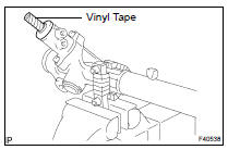
(m) Wrap vinyl tape around the spline of the control valve.
(n) Install the dust cover to the control valve housing.
45. INSTALL STEERING RACK END SUB-ASSY
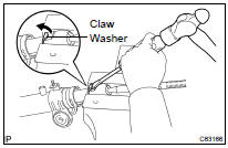
(a) Install 2 new claw washers, and temporarily install the 2 rack ends sub-assy.
HINT: Align the claws of the claw washer with the steering rack grooves.
(b) Using SST, install the 2 rack end sub-assy.
SST 09922-10010
Torque: 60 NVm (616 kgfVcm, 45 ftVlbf)
NOTICE: Use SST 09922-10010, following the direction shown in the illustration.
HINT:
- Using SST, hold the rack and install the rack end subassy.
- Use a torque wrench with a fulcrum length of 345 mm (13.58 in.).
(c) Using a brass bar and a hammer, stake the 2 claw washers.
NOTICE: Avoid any impact to the steering rack.
46. INSPECT STEERING RACK END SUB-ASSY
(a) Ensure that the holes of the rack ends are not clogged with grease.
HINT: If the hole is clogged, the pressure inside the boot will change after it is assembled and steering wheel is turned.
47. INSTALL STEERING RACK BOOT NO.2
48. INSTALL STEERING RACK BOOT NO.1
49. INSTALL STEERING RACK BOOT NO.2 CLAMP
(a) Using SST, tighten the rack boot No.2 clamp, as shown in the illustration.
SST 09521-24010
Clearance: 3.0 mm (0.118 in.) or less
NOTICE: Be careful not to damage the boot.
50. INSTALL STEERING RACK BOOT NO.1 CLAMP
SST 09521-24010
HINT: Perform the same procedure as for the No.2 clamp.
51. INSTALL STEERING RACK BOOT CLIP
(a) Using pliers, install the 2 boot clips.
52. INSTALL TIE ROD ASSY LH
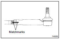
(a) Screw the lock nut and tie rod assy LH on the rack end until the matchmarks are aligned.
Torque: 74 NVm (750 kgfVcm, 54 ftVlbf)
HINT: After adjusting toe-in, torque the lock nut (see page 26-7 ).
53. INSTALL TIE ROD ASSY RH
HINT: Perform the same procedure as for the LH.
54. INSTALL STEERING LEFT TURN PRESSURE TUBE
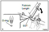
(a) Coat 2 new O-rings with power steering fluid and install them to the left turn pressure tube.
(b) Using SST, install the left turn pressure tube to the steering link assy.
SST 09023-38201
Torque: 11 NVm (116 kgfVcm, 8 ftVlbf)
HINT:
- Use a torque wrench with a fulcrum length of 300 mm (9.84 in.).
- This torque value is effective when SST is parallel to a torque wrench.
55. INSTALL STEERING RIGHT TURN PRESSURE TUBE
(a) Perform the same procedure as for the left turn pressure tube.
SST 09023-38201
(b) Install the tube clamp to the turn pressure tubes.
56. INSTALL POWER STEERING LINK ASSY
(a) Install the power steering link assy with the 2 bolts and the nuts.
Torque: 70 NVm (714 kgfVcm, 52 ftVlbf)
57. CONNECT PRESSURE FEED TUBE ASSY
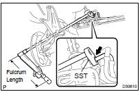
(a) Using SST, connect the pressure feed tube assy to the steering link assy.
SST 09023-12701
Torque: 22 NVm (230 kgfVcm, 16 ftVlbf)
HINT:
- Use a torque wrench with a fulcrum length of 300 mm (11.81 in.).
- This torque value is effective when SST is parallel to a torque wrench.
(b) Install the pressure feed tube assy clamp with the bolt.
Torque: 9.8 NVm (100 kgfVcm, 87 in.Vlbf)
58. CONNECT RETURN TUBE ASSY
(a) Using SST, connect the return tube assy to the steering link assy.
SST 09023-12701 Torque: 22 NVm (230 kgfVcm, 16 ftVlbf)
HINT:
- Use a torque wrench with a fulcrum length of 300 mm (11.81 in.).
- This torque value is effective when SST is parallel to a torque wrench.
(b) Install the tube clamp to the pressure feed tube assy.
(c) Install the return tube clamp with the nut.
Torque: 9.8 NVm (100 kgfVcm, 87 in.Vlbf)
59. INSTALL FRONT STABILIZER BRACKET NO.1 LH
(a) Install the stabilizer bar bush No.1 to the stabilizer bar.
(b) Install the stabilizer bracket No.1 LH and the stabilizer bracket No.2 with the 2 bolts.
Torque: 16 NVm (163 kgfVcm, 12 ftVlbf)
60. INSTALL FRONT STABILIZER BRACKET NO.1 RH
HINT: Perform the same procedure as for the LH.
61. CONNECT FRONT STABILIZER LINK ASSY LH (SEE PAGE 30-21 )
62. CONNECT FRONT STABILIZER LINK ASSY RH
HINT: Perform the same procedure as for the LH.
63. CONNECT STEERING INTERMEDIATE SHAFT SUB-ASSY
(a) Align the matchmarks on the intermediate shaft sub-assy and the steering link assy.
(b) Install the bolt.
Torque: 35 NVm (360 kgfVcm, 26 ftVlbf)
(c) Tighten bolt A.
Torque: 35 NVm (360 kgfVcm, 26 ftVlbf)
(d) Install the steering column hole cover No.2 to the steering hole cover No.1.
(e) Install the clamp to the steering column hole cover No.1 and tighten bolt B
64. CONNECT TIE ROD ASSY LH (SEE PAGE 30-21 )
65. CONNECT TIE ROD ASSY RH
HINT: Perform the same procedure as for the LH.
66. INSTALL FRONT WHEEL
Torque: 103 NVm (1,050 kgfVcm, 76 ftVlbf)
67. BLEED POWER STEERING FLUID (SEE PAGE 51-3 )
68. CHECK POWER STEERING FLUID LEAKAGE
69. INSPECT AND ADJUST FRONT WHEEL ALIGNMENT (SEE PAGE 26-7 )
70. PERFORM STEERING ANGLE SENSOR ZERO POINT CALIBRATION (SEE PAGE 05-765 )
71. INSPECT STEERING WHEEL CENTER POINT
 Vane pump ASSY (3MZ-FE)
COMPONENTS
OVERHAUL
NOTICE:
Do not overtighten when using a vise.
When installing, coat the parts indicated by the arrows with power
steering fluid
(see page 51-16 ).
1. REMOVE FRONT ...

More about Toyota Highlander:
Components
...
