Toyota Highlander Service Manual: Vane pump ASSY (2AZ-FE)
COMPONENTS
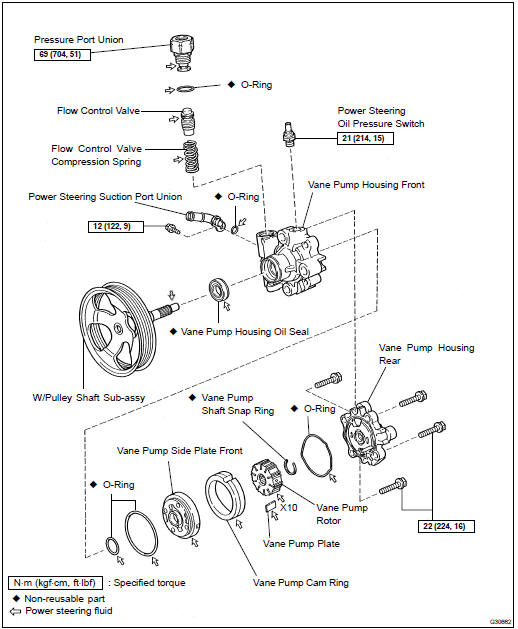
OVERHAUL
NOTICE:
- Do not overtighten when using a vise.
- When installing, coat the parts indicated by the arrows with power steering fluid (see page 51-7 ).
1. REMOVE FRONT WHEEL RH
2. DRAIN POWER STEERING FLUID
3. REMOVE FRONT FENDER APRON SEAL RH
4. REMOVE FAN AND GENERATOR V BELT (SEE PAGE 14-5 )
SST 09249-63010
5. DISCONNECT OIL RESERVOIR TO PUMP HOSE NO.1
(a) Remove the clip and disconnect the oil reservoir to pump hose No.1.
NOTICE: Take care not to spill fluid on the V belt.
6. DISCONNECT PRESSURE FEED TUBE ASSY
(a) Using a wrench (27 mm) to hold the pressure port union, remove the union bolt and the gasket.
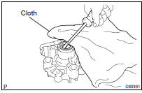
7. REMOVE VANE PUMP ASSY
(a) Disconnect the connector from the oil pressure switch.
(b) Using SST and a deep socket wrench (14 mm), loosen bolt A.
SST 09249-63010
(c) Remove bolt B and the vane pump assy.
8. FIX VANE PUMP ASSY
(a) Using SST, hold the vane pump assy in a vise.
SST 09630-00014 (09631-00132)
9. REMOVE POWER STEERING SUCTION PORT UNION
(a) Remove the bolt and the suction port union.
(b) Remove the O-ring from the suction port union.
10. REMOVE FLOW CONTROL VALVE
(a) Remove the pressure port union.
(b) Remove the O-ring from the pressure port union.
(c) Remove the flow control valve and the compression spring.
11. REMOVE POWER STEERING OIL PRESSURE SWITCH
NOTICE: If the oil pressure switch is dropped or damaged, replace it with a new one.
12. REMOVE VANE PUMP HOUSING REAR
(a) Remove the 4 bolts and the housing rear from the housing front.
(b) Remove the O-ring from the housing rear.
13. REMOVE W/PULLEY SHAFT SUB-ASSY
(a) Using 2 screwdrivers, remove the snap ring from the w/ pulley shaft sub-assy.
(b) Remove the w/pulley shaft sub-assy.
14. REMOVE VANE PUMP ROTOR
(a) Remove the 10 vane pump plates.
(b) Remove the vane pump rotor.
15. REMOVE VANE PUMP CAM RING
16. REMOVE VANE PUMP SIDE PLATE FRONT
(a) Remove the side plate front from the housing front.
(b) Remove the O-ring from the side plate front.
(c) Remove the O-ring from the housing front.
17. REMOVE VANE PUMP HOUSING OIL SEAL
(a) Using a screwdriver, remove the housing oil seal.
NOTICE: Be careful not to damage the housing front.
18. INSPECT VANE PUMP SHAFT AND BUSH IN HOUSING FRONT
(a) Using a micrometer and a caliper gauge, measure the oil clearance.
Maximum clearance: 0.07 mm (0.0028 in.)
If it is more than the maximum, replace the vane pump assy.
19. INSPECT VANE PUMP ROTOR AND VANE PUMP PLATES

(a) Using a micrometer, measure the thickness of the vane pump plates.
Minimum thickness: 1.405 to 1.411 mm (0.05531 to 0.05555 in.)
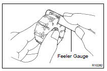
(b) Using a feeler gauge, measure the clearance between a side face of the vane pump rotor groove and the vane plates.
Maximum clearance: 0.03 mm (0.0012 in.)
If clearance exceeds maximum, replace the vane pump assy.
20. INSPECT FLOW CONTROL VALVE
(a) Coat the flow control valve with power steering fluid and check that it falls smoothly into the flow control valve hole under its own weight.
If it lacks smoothness, replace the vane pump assy.
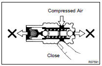
(b) Check the flow control valve for leakage. Close one of the holes and apply compressed air, 392 to 490 kPa (4 to 5 kgf/cm2, 57 to 71 psi), into the opposite side hole, and confirm that air does not come out from the both end holes.
If air leaks, replace the vane pump assy.
21. INSPECT FLOW CONTROL VALVE COMPRESSION SPRING
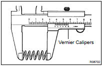
(a) Using vernier calipers, measure the free length of the compression spring.
Minimum free length: 30.3 mm (1.193 in.)
If it is less than the minimum, replace the vane pump assy.
22. INSPECT PRESSURE PORT UNION
If the union seat in the pressure port union is severely damaged, it may cause fluid leakage. In that case, replace the vane pump assy.
23. INSTALL VANE PUMP HOUSING OIL SEAL
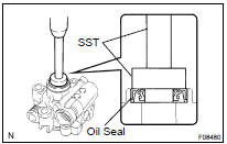
(a) Coat a new housing oil seal lip with power steering fluid.
(b) Using SST and a press, install a new housing oil seal.
SST 09950- 60010 (09951- 00280), 09950- 70010 (09951-07100)
NOTICE: Make sure that the housing oil seal is installed in the correct direction.
24. INSTALL W/PULLEY SHAFT SUB-ASSY
(a) Coat bushing surface of the housing front with power steering fluid.
(b) Gradually insert the w/pulley shaft sub-assy from the pulley side.
NOTICE:
- Do not damage the housing oil seal lip in the housing front.
- After inserting the w/pulley shaft sub-assy, check that the oil seal lip faces in the correct direction.
25. INSTALL VANE PUMP SIDE PLATE FRONT
(a) Coat a new O-ring with power steering fluid and install it into the housing front.
(b) Coat a new O-ring with power steering fluid and install it onto the side plate front.
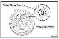
(c) Align the dent of the side plate front with that of the housing front, and install the side plate front.
NOTICE: Make sure that the side plate front is installed in the correct direction
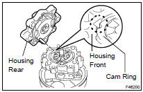
26. INSTALL VANE PUMP CAM RING
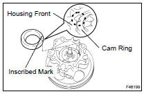
(a) Align the dent of the cam ring with that of the side plate front, and install the cam ring with the inscribed mark facing upward.
NOTICE: Make sure that the cam ring is installed in the correct direction.
27. INSTALL VANE PUMP ROTOR
(a) Install the vane pump rotor.
HINT: Vane pump rotor has no specific direction.
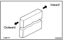
(b) Coat 10 vane pump plates with power steering fluid.
(c) Install the vane pump plates with the round end facing outward.
28. INSTALL VANE PUMP SHAFT SNAP RING
(a) Using a screwdriver and a snap ring expander, install a new snap ring to the w/pulley shaft sub-assy.
29. INSTALL VANE PUMP HOUSING REAR
(a) Coat a new O-ring with power steering fluid and install it onto the housing rear.
(b) Align the straight pin of the housing rear with the dents of the cam ring, side plate front and the housing front, and install the housing rear with the 4 bolts.
Torque: 22 NVm (224 kgfVcm, 16 ftVlbf)
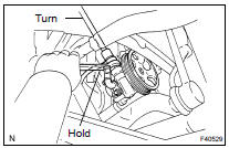
30. INSPECT PRELOAD
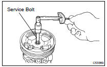
(a) Check that the pump rotates smoothly without abnormal noise.
(b) Temporarily install the service bolt.
Recommended service bolt: Thread diameter: 10 mm (0.39 in.) Thread pitch: 1.25 mm (0.0492 in.) Bolt length: 50 mm (1.97 in.)
(c) Using a torque wrench, check the pulley rotating torque.
Rotating torque: 0.27 NVm (2.8 kgfVcm, 2.4 in.Vlbf) or less
If the rotating torque is not as specified, check the housing oil seal.
31. INSTALL POWER STEERING OIL PRESSURE SWITCH
(a) Coat a new O-ring with power steering fluid and install it to the oil pressure switch.
(b) Install the oil pressure switch onto the vane pump assy.
Torque: 21 NVm (214 kgfVcm, 15 ftVlbf)
32. INSTALL FLOW CONTROL VALVE
(a) Coat the compression spring and the flow control valve with power steering fluid.
(b) Install the compression spring and the flow control valve.
(c) Coat a new O-ring with power steering fluid and install it onto the pressure port union.
(d) Install the pressure port union.
Torque: 69 NVm (704 kgfVcm, 51 ftVlbf)
33. INSTALL POWER STEERING SUCTION PORT UNION
(a) Coat a new O-ring with power steering fluid, and install it to the suction port union.
(b) Install the suction port union with the bolt.
Torque: 12 NVm (122 kgfVcm, 9 ftVlbf)
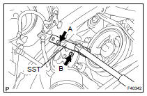
34. INSTALL VANE PUMP ASSY
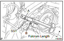
(a) Temporarily tighten bolt A to the vane pump assy.
(b) Install the vane pump assy and bolt B.
Torque: 37 NVm (377 kgfVcm, 27 ftVlbf)
(c) Using SST and a deep socket wrench (14 mm), tighten bolt A.
SST 09249-63010
Torque: 26 NVm (264 kgfVcm, 19 ftVlbf)
HINT:
- Use a torque wrench with a fulcrum length of 345 mm (13.58 in.).
- This torque value is effective when SST is parallel to a torque wrench.
(d) Connect the connector to the oil pressure switch.
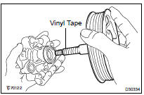
35. CONNECT PRESSURE FEED TUBE ASSY
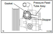
(a) Install the pressure feed tube assy and a new gasket to the vane pump assy with the union bolt.
HINT: Make sure the stopper of the pressure feed tube assy touches the housing front as shown in the illustration.
(b) Using a wrench (27 mm) to hold the pressure port union, torque the union bolt.
Torque: 52 NVm (525 kgfVcm, 38 ftVlbf)
36. CONNECT OIL RESERVOIR TO PUMP HOSE NO.1
(a) Connect the oil reservoir to pump hose No.1 with the clip.
NOTICE: Take care not to spill fluid on the V belt.
37. INSTALL FAN AND GENERATOR V BELT (SEE PAGE 14-5 )
SST 09249-63010
38. INSTALL FRONT FENDER APRON SEAL RH
39. INSTALL FRONT WHEEL RH
Torque: 103 NVm (1,050 kgfVcm, 76 ftVlbf)
40. BLEED POWER STEERING FLUID (SEE PAGE 51-3 )
41. INSPECT FLUID LEAK
 On-vehicle inspection
1. INSPECT DRIVE BELT
(a) Visually check the belt for excessive wear, frayed cords,
etc.
If any defect is found, replace the drive belt.
HINT:
Cracks on the rib side of a belt are considered ...
 Vane pump ASSY (3MZ-FE)
COMPONENTS
OVERHAUL
NOTICE:
Do not overtighten when using a vise.
When installing, coat the parts indicated by the arrows with power
steering fluid
(see page 51-16 ).
1. REMOVE FRONT ...
More about Toyota Highlander:
Overhaul
HINT:
COMPONENTS: See page 65-9
Use the same procedures for the RH side and LH side.
The procedures listed below are for the LH side.
Installation is in the reverse order of removal.
1. REMOVE RADIATOR GRILLE (SEE PAGE 76-2 )
2. REMOVE FRONT FENDER SPLASH SHIELD SUB-ASSY LH (SEE PAGE 7 ...
