Toyota Highlander Service Manual: Rear NO.1 Seat ASSY RH (W/rear NO.2 Seat)
COMPONENTS
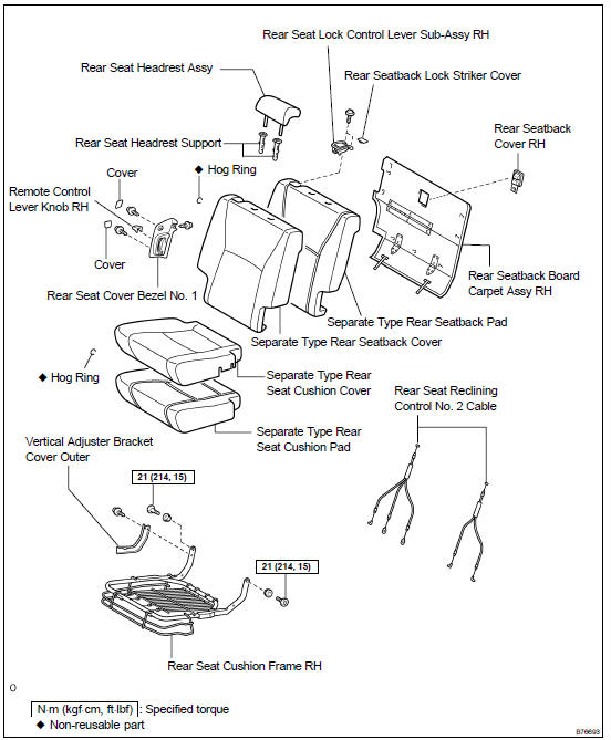
OVERHAUL
HINT:
- The installation procedures are the removal procedures in reverse order. However, only installation procedures requiring additional information are included.
- A bolt without a torque specification is shown in the standard bolt chart (see page 03-2 ).
1. REMOVE REAR SEAT TRACK BRACKET COVER OUTER
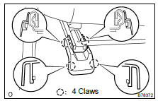
(a) Using a screwdriver, disengage the 4 claws and remove the 2 covers.
HINT: Tape the screwdriver tip before use.
2. REMOVE REAR SEAT TRACK BRACKET COVER INNER
HINT: Use the same procedures described for the bracket cover outer.
3. REMOVE REAR SEAT TRACK BRACKET COVER OUTER RH
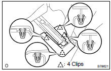
(a) Using a screwdriver, disengage the 4 clips and remove the cover.
HINT: Tape the screwdriver tip before use.
4. REMOVE REAR SEAT TRACK BRACKET COVER INNER RH
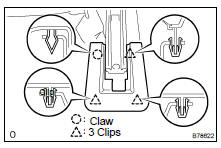
(a) Using a screwdriver, disengage the claw and 3 clips and remove the cover.
HINT: Tape the screwdriver tip before use.
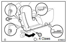
5. REMOVE REAR NO.1 SEAT ASSY RH
(a) Remove the headrest.
(b) Remove the 5 bolts and seat.
6. REMOVE REAR SEAT CUSHION MOULDING REAR RH
(a) Remove the 2 screws.
(b) Using a screwdriver, disengage the 4 claws and remove the moulding by pulling it out in the arrow mark direction shown in the illustration.
HINT: Tape the screwdriver tip before use.
7. REMOVE REAR SEAT CUSHION MOULDING RH
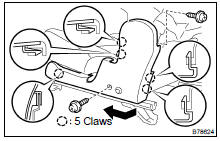
(a) Remove the 2 screws.
(b) Using a screwdriver, disengage the 5 claws and remove the moulding by pulling it out in the arrow mark direction shown in the illustration.
HINT: Tape the screwdriver tip before use.
8. REMOVE VERTICAL ADJUSTER BRACKET COVER OUTER
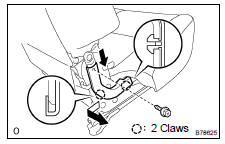
(a) Remove the screw.
(b) Disengage the 2 claws and remove the bracket cover by pulling it out in the arrow mark direction shown in the illustration.
9. REMOVE RECLINING HINGE COVER RH
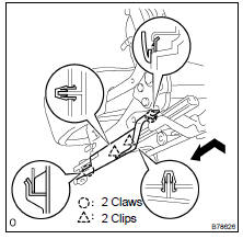
(a) Disengage the 2 clips and 2 claws and remove the hinge cover by pulling it out in the arrow mark direction shown in the illustration.
10. REMOVE REAR SEAT CUSHION ASSY RH
(a) Using a torx) socket wrench (T45), remove the 2 bolts.
(b) Remove the 2 bolts and cushion.
11. REMOVE SEPARATE TYPE REAR SEAT CUSHION COVER
(a) Disengage the hook and remove the cushion cover together with the pad from the cushion frame.
(b) Remove the hog rings and seat cushion cover.
12. REMOVE SEAT TRACK UPPER RAIL COVER RH
(a) Remove the 2 screws and rail cover.
13. REMOVE REMOTE CONTROL LEVER KNOB RH
(a) Remove the screw and control lever knob.
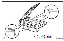
14. REMOVE REAR SEAT COVER BEZEL NO.1
(a) Using a screwdriver, disengage the 4 claws and remove the 2 covers.
HINT: Tape the screwdriver tip before use.
(b) Remove the 3 screws and seat cover bezel.
15. REMOVE TONNEAU COVER HOOK HOLDER
(a) Remove the 2 screws and 2 holders.
16. REMOVE REAR SEATBACK COVER RH
(a) Using a screwdriver, disengage the 4 claws and remove the seatback cover.
HINT: Tape the screwdriver tip before use.
17. REMOVE REAR SEATBACK BOARD CARPET ASSY RH
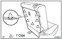
(a) Using a clip remover, disengage the 7 clips and remove seatback board carpet.
18. REMOVE REAR SEAT LOCK CONTROL LEVER SUB-ASSY RH

(a) Using a screwdriver, disengage the 2 claws and remove the seat lock control lever cover.
HINT: Tape the screwdriver tip before use.
(b) Remove the 2 screws.
(c) Disconnect the reclining remote control cable and remove the seat lock control lever.
19. REMOVE SEPARATE TYPE REAR SEATBACK COVER
(a) Remove the 2 headrest supports.
(b) Using a clip remover, remove the 2 clips.
(c) Disengage the hook and remove the seatback cover together with the pad from the seatback frame.
(d) Remove the hog rings and seatback cover.
20. DISCONNECT REAR SEAT RECLINING CONTROL NO. 2 CABLE
21. REMOVE REAR SEAT BELT ASSY INNER (See page 61-15 )
22. REMOVE REAR SEAT RECLINING COVER INNER RH

(a) Remove the screw and reclining cover by pulling out the cover in the arrow mark direction shown in the illustration.
23. REMOVE RECLINING ADJUSTER INSIDE COVER RH
(a) Remove the screw and inside cover.
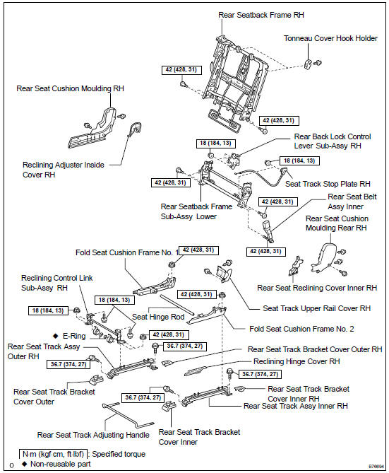
24. REMOVE REAR SEATBACK FRAME ASSY RH
(a) Using a torx) socket wrench (T40), remove the 4 torx) bolts and seatback frame.
25. REMOVE RECLINING CONTROL LINK SUB-ASSY RH
(a) Remove the 4 nuts and control link.
26. REMOVE SEAT TRACK STOP PLATE RH
(a) Remove the 2 nuts and stop plate.
27. REMOVE REAR BACK LOCK CONTROL LEVER SUB-ASSY RH
(a) Remove the 3 nuts and control lever.
28. REMOVE REAR SEATBACK FRAME SUB-ASSY LOWER LH
(a) Outer side: Using a torx) socket wrench (T40), remove the 3 torx) bolts.
(b) Inner side: Using a torx) socket wrench (T55), remove the 2 torx) bolts and seatback frame.
29. REMOVE FOLD SEAT CUSHION FRAME NO.1
(a) Remove the 2 nuts and cushion frame.
30. REMOVE FOLD SEAT CUSHION FRAME NO.2
(a) Remove the 2 nuts and cushion frame.
31. REMOVE REAR SEAT TRACK ADJUSTING HANDLE
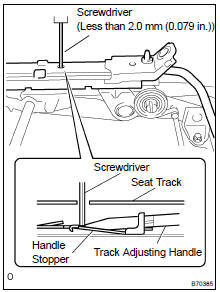
(a) Using a screwdriver, push down the handle stopper to disengage the claw with the slide rail in the frontmost position.
Remove the track adjusting handle.
32. INSTALL FOLD SEAT CUSHION FRAME NO.1
(a) Install the cushion frame with the 2 nuts.
Torque: 42 NVm (428 kgfVcm, 31 ftVlbf)
33. INSTALL FOLD SEAT CUSHION FRAME NO.2
(a) Install the cushion frame with the 2 nuts.
Torque: 42 NVm (428 kgfVcm, 31 ftVlbf)
34. INSTALL REAR SEATBACK FRAME SUB-ASSY LOWER LH
(a) Outer side: Using a torx) socket wrench (T40), install the 3 torx) bolts.
Torque: 42 NVm (428 kgfVcm, 31 ftVlbf)
(b) Inner side: Using a torx) socket wrench (T55), install the seatback frame with the 2 torx) bolts.
Torque: 42 NVm (428 kgfVcm, 31 ftVlbf)
35. INSTALL REAR SEATBACK FRAME ASSY RH
(a) Using a torx) socket wrench (T40), install the seatback frame with the 4 torx) bolts.
Torque: 42 NVm (428 kgfVcm, 31 ftVlbf)
36. INSTALL REAR BACK LOCK CONTROL LEVER SUB-ASSY RH
(a) Install the control lever with the 3 nuts.
Torque: 18 NVm (184 kgfVcm, 13 ftVlbf)
37. INSTALL SEAT TRACK STOP PLATE RH
(a) Install the stop plate with the 2 nuts.
Torque: 18 NVm (184 kgfVcm, 13 ftVlbf)
38. INSTALL RECLINING CONTROL LINK SUB-ASSY RH
(a) Install the control link with the 4 nuts.
Torque: 42 NVm (428 kgfVcm, 31 ftVlbf)
39. INSTALL REAR SEAT BELT ASSY INNER (See page 61-15 )
40. INSTALL SEPARATE TYPE REAR SEATBACK COVER
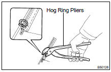
(a) Using hog ring pliers, install the seatback cover to the seatback pad with new hog rings.
(b) Install the seatback cover to the seatback frame.
NOTICE:
- Be careful not to damage the cover.
- When installing the hog rings, take care to prevent wrinkles as much as possible.
(c) Install the 2 headrest supports.
41. INSTALL SEPARATE TYPE REAR SEAT CUSHION COVER
(a) Using hog ring pliers, install the cushion cover to the cushion pad with new hog rings.
NOTICE: Be careful not to damage the cover.
When installing the hog rings, take care to prevent wrinkles as much as possible.
(b) Install the cushion cover to the cushion frame.
42. INSTALL REAR SEAT CUSHION ASSY RH
(a) Using a torx) socket wrench (T45), install seat cushion with the 2 torx) bolts.
Torque: 21 NVm (214 kgfVcm, 15 ftVlbf) for hinge side
(b) Install the seat cushion with the 2 bolts.
Torque: 18 NVm (184 kgfVcm, 13 ftVlbf) for cushion side
43. INSTALL REAR NO.1 SEAT ASSY RH
(a) Place the seat in the cabin.
(b) Install the seat with the 4 bolts.
Torque: 36.7 NVm (375 kgfVcm, 27 ftVlbf)
(c) Install the fold seat stopper band with the bolt on the vehicle side.
Torque: 9.0 NVm (92 kgfVcm, 80 in.Vlbf)
(d) Install the headrest.
(e) When sliding the seat, check that both sides of the adjuster lock simultaneously.
HINT: Check that the seat adjuster locks.
 Rear NO.1 Seat ASSY LH (W/rear NO.2 Seat)
COMPONENTS
OVERHAUL
HINT:
The installation procedures are the removal procedures in reverse
order. However, only installation
procedures requiring additional information are included.
...
 Rear NO.2 seat ASSY
COMPONENTS
OVERHAUL
HINT:
The installation procedures are the removal procedures in reverse
order. However, only installation
procedures requiring additional information are included.
A ...
More about Toyota Highlander:
Back door glass
COMPONENTS
REPLACEMENT
HINT:
The installation procedures are the removal procedures in reverse
order. However, only installation
procedures requiring additional information are included.
A bolt without a torque specification is shown in the standard bolt
chart (see page 03-2 ).
...
