Toyota Highlander Service Manual: Rear drive shaft (4WD)
OVERHAUL
HINT: COMPONENTS: SEE PAGE 30-4 Overhaul the RH side using the same procedures as for the LH side.
1. REMOVE REAR WHEEL
2. SEPARATE SPEED SENSOR REAR LH
(a) Remove the bolt and the speed sensor from the axle carrier.
NOTICE:
- Be careful not to damage the speed sensor.
- Prevent foreign matter from adhering to the speed sensor.
3. REMOVE REAR AXLE SHAFT LH NUT
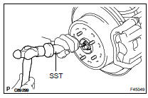
(a) Using SST and a hammer, unstake the staked part of the axle shaft LH nut.
SST 09930-00010
NOTICE: Loosen the staked part of the nut completely, otherwise the screw of the drive shaft may be damaged.
(b) While applying the brakes, remove the lock axle shaft LH nut.
4. SEPARATE REAR SUSPENSION ARM ASSY NO.1 LH (SEE PAGE 30-60 )
5. SEPARATE STRUT ROD ASSY REAR (SEE PAGE 30-60 )
6. SEPARATE REAR SUSPENSION ARM ASSY NO.2 LH (SEE PAGE 30-60 )
7. SEPARATE REAR AXLE CARRIER SUB-ASSY LH
(a) Push the rear axle carrier sub-assy LH toward the outside of the vehicle, using a plastic hammer, separate the rear drive shaft assy LH from the rear axle carrier sub-assy LH.
NOTICE:
- Be careful not to damage the joint boot and speed sensor rotor.
- Do not push out the rear axle carrier sub-assy LH excessively.
8. REMOVE REAR DRIVE SHAFT ASSY LH
(a) Remove the rear drive shaft, as shown in the illustration.
NOTICE: Move the drive shaft assy while keeping it level.
9. INSPECT REAR DRIVE SHAFT ASSY LH
(a) Check that there is no remarkable play in the radial direction of the outboard joint.
(b) Check that the inboard joint slides smoothly in the thrust direction.
(c) Check that there is no remarkable play in the radial direction of the inboard joint.
(d) Check the boots for damage.
10. REMOVE REAR DRIVE SHAFT INBOARD JOINT BOOT LH CLAMP
(a) Using pliers, remove the inboard joint boot LH clamp, as shown in the illustration.
11. REMOVE REAR DRIVE SHAFT INBOARD JOINT BOOT RH NO.2 CLAMP
(a) Using pliers, remove the inboard joint boot LH No.2 clamp, as shown in the illustration.
12. SEPARATE INBOARD JOINT BOOT
(a) Separate the inboard joint boot from the inboard joint assy.
13. REMOVE REAR DRIVE SHAFT INBOARD JOINT ASSY LH
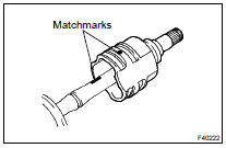
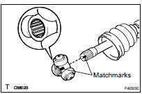
(a) Put matchmarks on the inboard joint assy and outboard joint shaft.
NOTICE: Do not punch the marks.
(b) Remove the inboard joint assy from the outboard joint shaft.
(c) Using a snap ring expander, remove the snap ring.
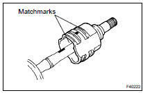
(d) Put matchmarks on the outboard joint shaft and tripod joint.
NOTICE: Do not punch the marks.
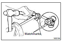
(e) Using a brass bar and a hammer, remove the tripod joint from the outboard joint shaft.
NOTICE: Do not tap the roller.
(f) Remove the inboard joint boot, inboard joint boot LH clamp and inboard joint boot LH No.2 clamp.
14. REMOVE REAR DRIVE SHAFT OUTBOARD JOINT BOOT LH CLAMP
(a) Using pliers, remove the outboard joint boot LH clamp, as shown in the illustration.
15. REMOVE REAR DRIVE SHAFT OUTBOARD JOINT BOOT LH NO.2 CLAMP
(a) Using pliers, remove the outboard joint boot LH No.2 clamp, as shown in the illustration.
16. REMOVE OUTBOARD JOINT BOOT
(a) Remove the outboard joint boot from the outboard joint shaft.
(b) Remove the old grease from the outboard joint.
NOTICE: Do not disassemble the outboard joint.
17. REMOVE REAR DRIVE SHAFT INBOARD JOINT LH SHAFT SNAP RING
(a) Using a screwdriver, remove the shaft snap ring.
18. REMOVE REAR DRIVE SHAFT DUST COVER LH
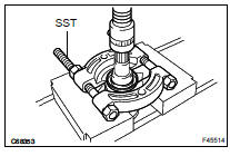
(a) Using SST and a press, remove the drive shaft dust cover LH.
SST 09950-00020
NOTICE: Be careful not to drop the inboard joint assy.
Do not overtighten the SST.
19. INSTALL REAR DRIVE SHAFT DUST COVER LH
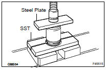
(a) Using SST and a steel plate, install a new drive shaft dust cover LH SST 09527-2101 1
NOTICE:
- Dust cover should be completely installed.
- Be careful not to damage the dust cover.
20. INSTALL REAR DRIVE SHAFT INBOARD JOINT LH SHAFT SNAP RING
(a) Install a new hole snap ring.
21. INSTALL OUTBOARD JOINT BOOT
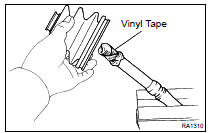
HINT: Before installing the boot, wrap the spline of the outboard joint shaft with vinyl tape to prevent the boot from being damaged.
(a) Install a new outboard joint boot, 2 outboard joint boot clamps, 2 inboard joint boot clamps and inboard joint boot.
(b) Make sure that the 2 boots are on the shaft groove.
22. INSTALL REAR DRIVE SHAFT OUTBOARD JOINT BOOT LH CLAMP
(a) Hold the drive shaft lightly in a soft vise.
(b) Install the 2 outboard joint boot clamps to the boot.
HINT: Before installing the clamps, pack the outboard joint and boot with grease in the boot kit.
Grease capacity: 95 to 105 g (3.4 to 3.7 oz.)
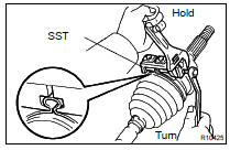
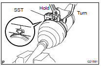
(c) Place SST onto the outboard joint boot LH clamp.
SST 09521-24010
(d) Tighten the SST so that the outboard joint boot LH clamp is pinched.
NOTICE: Do not overtighten the SST.
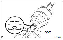
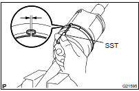
(e) Using SST, measure the clearance of the outboard joint boot LH clamp.
SST 09240-00020
Clearance: 1.3 mm (0.051 in.) or less
NOTICE: When the measured value is greater than the specified value, retighten the clamp.
23. INSTALL REAR DRIVE SHAFT OUTBOARD JOINT BOOT LH NO.2 CLAMP
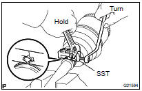
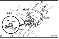
(a) Place SST onto the outboard joint boot LH No.2 clamp.
SST 09521-24010
(b) Tighten the SST so that the outboard joint boot LH No.2 clamp is pinched.
NOTICE: Do not overtighten the SST.
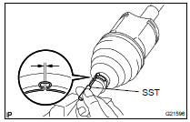
(c) Using SST, measure the clearance of the outboard joint boot LH No.2 clamp.
SST 09240-00020
Clearance: 1.3 mm (0.051 in.) or less
NOTICE: When the measured value is greater than the specified value, retighten the clamp.
24. INSTALL REAR DRIVE SHAFT INBOARD JOINT ASSY LH
(a) Place the beveled side of the tripod joint axial spline toward the outboard joint shaft.
(b) Align the matchmarks.
(c) Using a brass bar and a hammer, tap in the tripod joint to the outboard joint shaft.
NOTICE:
- Do not tap the roller.
- Be sure to install the tripod joint assy in the correct direction.
(d) Using a snap ring expander, install a new shaft snap ring.
(e) Pack the outboard joint shaft and boot with grease.
Grease capacity : 125.5 to 135.5 g (4.4 to 4.7 oz.)
(f) Align the matchmarks, install the inboard joint assy to the outboard joint shaft assy.
25. INSTALL INBOARD JOINT BOOT
(a) Install the inboard joint boot to the outboard joint shaft.
26. INSTALL REAR DRIVE SHAFT INBOARD JOINT BOOT LH CLAMP
(a) Install the inboard joint boot LH clamp.
- Hold the drive shaft lightly in a soft vise.
- Install the 2 inboard joint boot clamps to the boot.
- Place SST onto the inboard joint boot LH clamp.
SST 09521-24010
- Tighten the SST so that the inboard joint boot LH clamp is pinched.
NOTICE: Do not overtighten the SST.
- Using SST, measure the clearance of the inboard joint boot LH clamp.
SST 09240-00020
Clearance: 1.1 mm (0.043 in.) or less
NOTICE: When the measured value is greater than the specified value, retighten the clamp.
27. INSTALL REAR DRIVE SHAFT INBOARD JOINT BOOT LH NO.2 CLAMP
(a) Install the inboard joint boot LH No.2 clamp.
(b) Place SST onto the inboard joint boot LH No.2 clamp.
SST 09521-24010
(c) Tighten the SST so that the inboard joint boot LH No.2 clamp is pinched.
NOTICE: Do not overtighten the SST.
- (1) Using SST, measure the clearance of the inboard joint boot LH No.2 clamp.
SST 09240-00020
Clearance: 1.1 mm (0.043 in.) or less
NOTICE: When the measured value is greater than the specified value, retighten the clamp.
28. INSPECT REAR DRIVE SHAFT ASSY LH
(a) Check that there is no remarkable play in the radial direction of the outboard joint.
(b) Check that the inboard joint slides smoothly in the thrust direction.
(c) Check that there is no remarkable play in the radial direction of the inboard joint.
(d) Check the boots for damage.
29. INSTALL REAR DRIVE SHAFT ASSY LH
(a) Align the shaft splines and install the drive shaft assy with a brass bar and a hammer.
NOTICE:
- Set the snap ring with the opening side facing downward.
- Be careful not to damage the oil seal boot and dust cover.
- Move the drive shaft assy while keeping it level.
30. INSTALL REAR AXLE CARRIER SUB-ASSY LH
(a) Push the rear axle carrier sub-assy LH toward the inside of the vehicle fitting it to the splined part of the rear drive shaft assy LH and insert.
NOTICE: Be careful not to damage the joint boot and speed sensor rotor.
31. TEMPORARILY TIGHTEN REAR SUSPENSION ARM ASSY NO.2 LH (SEE PAGE 30-60 )
32. TEMPORARILY TIGHTEN STRUT ROD ASSY REAR (SEE PAGE 30-60 )
33. TEMPORARILY TIGHTEN REAR SUSPENSION ARM ASSY NO.1 LH (SEE PAGE 30-60 )
34. INSTALL REAR AXLE SHAFT LH NUT
(a) Install a new axle shaft LH nut.
Torque: 294 NVm, (3,000 kgfVcm, 217 ftVlbf) (b) Using a chisel and a hammer, stake the axle shaft LH nut.
35. INSTALL SPEED SENSOR REAR LH
(a) Install the speed sensor with the bolt.
Torque: 8.0 NVm (82 kgfVcm, 71 in.Vlbf)
NOTICE:
- Be careful not to damage the speed sensor.
- Prevent foreign matter from adhering to the speed sensor.
- Do not twist the sensor wire when installing the sensor.
36. INSTALL REAR WHEEL Torque: 103 NVm (1,050 kgfVcm, 76 ftVlbf)
37. STABILIZE SUSPENSION (SEE PAGE 27-29 )
38. FULLY TIGHTEN REAR SUSPENSION ARM ASSY NO.2 LH (SEE PAGE 27-25 )
39. FULLY TIGHTEN STRUT ROD ASSY REAR (SEE PAGE 27-13 )
40. FULLY TIGHTEN REAR SUSPENSION ARM ASSY NO.1 LH (SEE PAGE 27-18 )
41. INSPECT AND ADJUST REAR WHEEL ALIGNMENT (SEE PAGE 27-5 )
42. CHECK ABS SPEED SENSOR SIGNAL (SEE PAGE 05-765 )
 Front axle LH hub bolt
REPLACEMENT
HINT:
COMPONENTS:SEE PAGE 30-4
Replace the RH side by the same procedures with LH side.
1. REMOVE FRONT WHEEL
2. SEPARATE FRONT DISC BRAKE CALIPER ASSY
LH(SEE PAGE 30-38 )
3. REMOVE ...
 Rear axle hub & bearing ASSY LH (FF)
REPLACEMENT
HINT:
COMPONENTS: SEE PAGE 30-4
Replace the RH side by the same procedures with LH side.
1. REMOVE REAR WHEEL
2. SEPARATE RR DISC BRAKE CALIPER ASSY RH
(a) Remove the bolt and se ...
More about Toyota Highlander:
Cup holders
Front
Rear (second seats)
Type a
Pull the armrest down.
Type b
Fold the side table up for use.
Rear (third seats)
Removing the cup holder insert (front cup holder)
The cup holder insert may be removed for
cleaning.
Warning
Do not place anything other t ...
