Toyota Highlander Service Manual: Parking brake ASSY
COMPONENTS
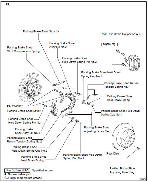
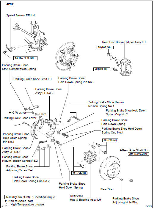
OVERHAUL
HINT:
- Use the same procedures for the RH side and LH side.
- The procedures listed below are for the LH side.
1. REMOVE REAR WHEEL
2. SEPARATE REAR DISC BRAKE CALIPER ASSY LH
(a) Remove the 2 bolts and separate the rear disc brake caliper assy LH.
HINT: Do not disconnect the flexible hose from the disc brake caliper assy LH.
3. REMOVE REAR DISC
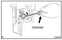
(a) Release the parking brake, and remove the rear disc.
HINT: If the disc cannot be removed easily, turn the shoe adjuster until the wheel turns freely.
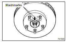
(b) Place machmarks on the rear disc and the axle hub.
(c) Remove the rear disc.
4. INSPECT BRAKE DISC INSIDE DIAMETER
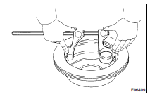
(a) Using a brake drum gauge or equivalent tool, measure the inside diameter of the rear disc.
Standard inside diameter: 190 mm (7.480 in.) Maximum inside diameter: 191 mm (7.520 in.)
If the inside diameter exceeds the maximum, replace the brake disc.
5. REMOVE PARKING BRAKE SHOE RETURN TENSION SPRING
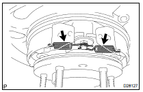
(a) Using needle-nose pliers, remove the 2 parking brake shoe return tension springs No.1.
6. REMOVE PARKING BRAKE SHOE STRUT LH
(a) Remove the parking brake shoe strut LH and the parking brake shoe strut compression spring.
7. REMOVE PARKING BRAKE SHOE ASSY LH NO.1
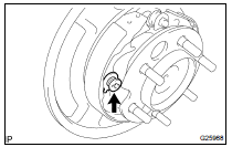
(a) Remove the parking brake shoe hold down spring cup No.1, parking brake shoe hold down spring and parking brake shoe hold down spring cup No.2.
(b) FF: Remove the parking brake shoe hold down spring pin No.1.
(c) Disconnect the parking brake shoe return spring No.2 and remove the parking brake shoe assy LH No.1.
8. REMOVE PARKING BRAKE SHOE ADJUSTING SCREW SET
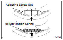
(a) Remove the parking brake shoe adjusting screw set.
(b) Remove the parking brake shoe return tension spring No.2.
9. REMOVE PARKING BRAKE SHOE ASSY LH NO.2
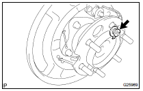
(a) Remove the parking brake shoe hold down spring cup No.1, parking brake shoe hold down spring, parking brake shoe hold down spring cup No.2 and parking brake shoe hold down spring pin No.2.
(b) Remove the parking brake shoe assy LH No.2.
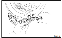
(c) Using needle-nose pliers, disconnect the parking brake cable No.3 from the parking brake cable shoe lever.
NOTICE: Be careful not to damage parking brake cable No.3.
10. SEPARATE SPEED SENSOR REAR LH (4WD DRIVE TYPE) (SEE PAGE 30-60 )
11. REMOVE REAR AXLE SHAFT LH NUT (4WD DRIVE TYPE) (SEE PAGE 30-60 )
SST 09930-00010
12. REMOVE REAR AXLE HUB & BEARING ASSY LH (4WD DRIVE TYPE) (SEE PAGE 30-60 )
13. REMOVE PARKING BRAKE SHOE HOLD DOWN SPRING PIN (4WD DRIVE TYPE)
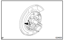
(a) Remove the parking brake shoe hold down spring pin No.1.
14. REMOVE PARKING BRAKE SHOE TYPE C WASHER
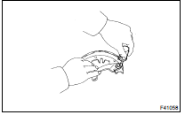
(a) Using a screwdriver, remove the C-washer.
(b) Remove the shim and parking brake shoe lever from parking brake shoe assy LH No.2.
15. INSPECT PARKING BRAKE SHOE LINING THICKNESS
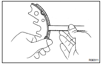
(a) Using a ruler, measure the thickness of the shoe lining.
Standard thickness: 2.5 mm (0.098 in.) Minimum thickness: 1.0 mm (0.039 in.)
If the lining thickness is less than or equal to the minimum, or if there is severe or uneven wear, replace the brake shoe.
16. INSPECT BRAKE DISC AND PARKING BRAKE SHOE LINING FOR PROPER CONTACT

(a) Apply chalk to the inside surface of the disc, then grind down the brake shoe lining to fit disc.
If the contact between the brake disc and the shoe lining is improper, repair it using a brake shoe grinder or replace the brake shoe assembly.
17. INSTALL PARKING BRAKE SHOE TYPE C WASHER

(a) Using a feeler gauge, measure the clearance.
Standard clearance: Less than 0.35 mm (0.014 in.)
If the clearance is not within the specifications, replace the shim with one of the correct size.


(b) Using pliers, install the parking brake shoe lever LH and the shim with a new C-washer.
18. APPLY HIGH TEMPERATURE GREASE
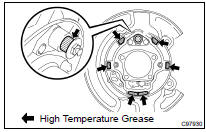
(a) Apply high temperature grease to the shaded parts shown in the illustration of the backing plate which make contact with the shoe.
19. INSTALL PARKING BRAKE SHOE HOLD DOWN SPRING PIN (4WD DRIVE TYPE)
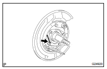
(a) Install the parking brake shoe hold down spring pin No.1.
20. INSTALL REAR AXLE HUB & BEARING ASSY LH (4WD DRIVE TYPE) (SEE PAGE 30-60 )
21. INSTALL REAR AXLE SHAFT LH NUT (4WD DRIVE TYPE) (SEE PAGE 30-60 )
22. INSTALL SPEED SENSOR REAR LH (4WD DRIVE TYPE) (SEE PAGE 30-60 )
23. INSTALL PARKING BRAKE SHOE ASSY LH NO.2
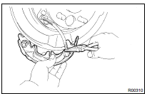
(a) Using needle-nose pliers, connect the parking brake cable No.3 to the parking brake cable shoe lever.
NOTICE: Be careful not to damage the parking brake cable No.3.
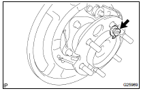
(b) Install the parking brake shoe assy LH No.2 with the parking brake shoe hold down spring, parking brake shoe hold down spring cup No.1, parking brake shoe hold down spring cup No.2 and parking brake shoe hold down spring pin No.2.
24. INSTALL PARKING BRAKE SHOE ADJUSTING SCREW SET
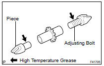
(a) Apply high temperature grease to the parking brake shoe adjusting bolt and piece.
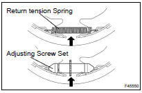
(b) Attach the parking brake shoe return tension spring No.2 to parking brake shoe assy LH No.1 and parking brake shoe assy LH No.2.
(c) Attach the parking brake shoe adjusting screw set to the parking brake shoe assy LH No.1 and parking brake shoe assy LH No.2.
25. INSTALL PARKING BRAKE SHOE ASSY LH NO.1
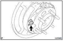
(a) FF: Install the parking brake shoe hold down spring pin No.1.
(b) Install the parking brake shoe assy LH No.1 with the parking brake shoe hold down spring, parking brake shoe hold down spring cup No.2, parking brake shoe hold down spring cup No.2.
26. INSTALL PARKING BRAKE SHOE STRUT LH
(a) Attach the parking brake shoe strut LH and the parking brake shoe strut compression spring to parking brake shoe assy LH No.2 and parking brake shoe assy LH No.1.
27. INSTALL PARKING BRAKE SHOE RETURN TENSION SPRING
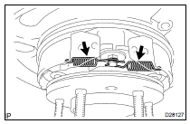
(a) Using needle-nose pliers, install the 2 return tension springs No.1 as shown in the illustration.
HINT: First install the front side spring then the rear side spring.
28. CHECK PARKING BRAKE INSTALLATION
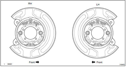
(a) Check that each part is installed properly.
NOTICE: There should be no oil or grease on the friction surface of the shoe lining and disc
29. INSPECT BEARING BACKLASH (4WD DRIVE TYPE) (SEE PAGE 30-3 )
30. INSPECT AXLE HUB DEVIATION (4WD DRIVE TYPE) (SEE PAGE 30-3 )
31. INSTALL REAR DISC
(a) Aligning the matchmarks, install the rear disc.
32. ADJUST PARKING BRAKE SHOE CLEARANCE
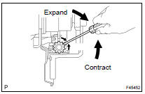
(a) Temporarily install the hub nuts.
(b) Remove the hole plug, turn the adjuster and expand the shoes until the disc locks.
(c) Contract the shoe adjuster until the disc rotates smoothly.
Standard : Return 8 notches (d) Check that the shoe has no brake drag.
(e) Install the hole plug.
33. CONNECT REAR DISC BRAKE CALIPER ASSY LH
(a) Install the rear disc brake caliper assy LH with the 2 bolts.
Torque: 78 NVm (800 kgfVcm, 58 ftVlbf)
34. INSTALL REAR WHEEL
Torque: 103 NVm (1,050 kgfVcm, 76 ftVlbf)
35. INSPECT PARKING BRAKE PEDAL TRAVEL (SEE PAGE 33-2 )
36. ADJUST PARKING BRAKE PEDAL TRAVEL (SEE PAGE 33-2 )
37. CHECK ABS SPEED SENSOR SIGNAL (4WD DRIVE TYPE) (SEE PAGE 05-765 )
 Parking brake cable ASSY NO.3
COMPONENTS
REPLACEMENT
HINT:
For parking brake cable No.2, employ the same procedure to the No.3 side.
1. REMOVE REAR WHEEL
2. SEPARATE REAR DISC BRAKE CALIPER ASSY LH
(a) Remove the 2 b ...
More about Toyota Highlander:
The keys
The following keys are provided with the vehicle.
vehicles without a smart key system
master keys
operating the wireless remote control
function
Valet key
key number plate
Vehicles with a smart key system
electronic keys
operating the smart key syst ...

