Toyota Highlander Service Manual: Instrument panel safety pad sub-ASSY
PRECAUTION
1. PRECAUTION FOR VEHICLE WITH SRS AIRBAG AND SEAT BELT PRETENSIONER
(a) Some operations in this section may affect the SRS airbags. Prior to performing the corresponding operations, read the SRS airbag NOTICE (see page 60-1 ).
REPLACEMENT
HINT: COMPONENTS: SEE PAGE 71-6
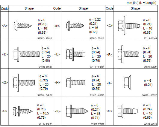
1. TABLE OF BOLT, SCREW AND NUT
HINT: The bolts, screws and nuts necessary for installation and removal of the instrument panel, are illustrated below and alphabetically coded.
2. DISCONNECT BATTERY NEGATIVE TERMINAL (SEE PAGE 60-1 )
3. PLACE FRONT WHEELS FACING STRAIGHT AHEAD
4. REMOVE STEERING WHEEL COVER LOWER NO.2
5. REMOVE STEERING WHEEL COVER LOWER NO.3
6. REMOVE HORN BUTTON ASSY (SEE PAGE 60-17 )
7. REMOVE STEERING WHEEL ASSY (SEE PAGE 50-8 )
SST 09950-50013 (09951-05010, 09952-05010, 09953-05020, 09954-05021)
8. REMOVE STEERING COLUMN COVER LWR (SEE PAGE 50-8 )
9. REMOVE STEERING COLUMN COVER UPR (SEE PAGE 50-8 )
10. REMOVE HEADLAMP DIMMER SWITCH ASSY (SEE PAGE 65-25 )
11. REMOVE WINDSHIELD WIPER SWITCH ASSY (SEE PAGE 66-16 )
12. REMOVE INSTRUMENT CLUSTER FINISH PANEL SUB-ASSY CENTER
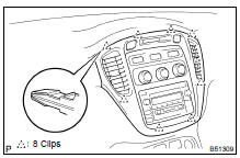
(a) Using a moulding remover, disengage the 8 clips.
(b) Disconnect the connectors, then remove the instrument cluster finish panel sub-assy center.
HINT: Set the shift lever in the N position.
13. REMOVE INTEGRATION CONTROL & PANEL ASSY (W/O NAVIGATION SYSTEM) (SEE PAGE 55-26 )
14. REMOVE MULTI-DISPLA Y (CRT DISPLAY) DISPLAY (W/ NAVIGATION SYSTEM) (SEE PAGE 67-8 )
15. REMOVE INSTRUMENT PANEL FINISH PANEL LOWER
(a) Using a moulding remover, disengage the 5 clips.
(b) Disconnect the connectors, then remove the instrument panel finish panel lower
16. REMOVE INSTRUMENT CLUSTER FINISH PANEL ASSY
(a) Using a moulding remover, disengage the 5 clips, then remove the instrument cluster finish panel assy.
17. REMOVE INSTRUMENT CLUSTER FINISH PANEL GARNISH
(a) Remove the 4 screws <B>.
(b) Disengage the claw, then remove the instrument cluster finish panel garnish.
18. REMOVE COMBINATION METER ASSY
(a) Remove the 3 screws <B>, then pull the combination meter assy.
(b) Disconnect the connectors, then remove the combination meter assy.
19. REMOVE INSTRUMENT PANEL FINISH PANEL SUB-ASSY LOWER
(a) Remove the 2 bolts <D>.
(b) Disengage the 3 clips.
(c) Disconnect the connectors.
(d) Disconnect the hood lock control cable, then remove the instrument panel finish panel sub-assy lower.
20. REMOVE INSTRUMENT PNL INSERT SUB- ASSY LWR LH
(a) Remove the 3 bolts <F> and the instrument panel insert sub-assy LWR LH.
21. REMOVE INSTRUMENT CLUSTER FINISH PANEL ASSY CENTER
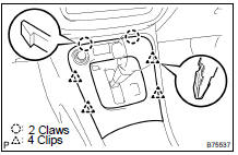
(a) Using a moulding remover, disengage the 4 clips and the 2 claws.
(b) Disconnect the connectors, then remove the instrument cluster finish panel assy center.
HINT: Set the shift lever in the N position.
22. REMOVE FLOOR CARPET COVER CENTER LH
(a) Remove the 2 clips and the floor carpet cover center LH.
23. REMOVE FLOOR CARPET COVER CENTER RH
24. REMOVE FRONT SEAT ARMREST ASSY CENTER
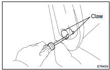
(a) Using a screwdriver, disengage the 2 claws and remove the seat armrest cover LH.
HINT: Tape the screwdriver tip, before use.
(b) Remove the bolt and front seat armrest assy center.
25. REMOVE CONSOLE BOX ASSY
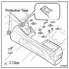
(a) Cover the parts indicated in the illustration with protective tape to prevent them from being damaged.
(b) Remove the 3 screws <B>.
(c) Remove the 2 console caps and the 2 screws <J>.
(d) Remove the 2 bolts <K>.
(e) Pull the console box assy towards the rear of the vehicle and disengage the 2 clips, and then remove the console box assy.
NOTICE: Be careful not to damage the bottom of the instrument panel safety pad when removing the console box assy.
26. REMOVE GLOVE COMPARTMENT DOOR ASSY
(a) Remove the glove compartment door damper clip.
(b) Remove the 2 clips and the glove compartment door assy.
27. REMOVE INSTRUMENT PANEL FINISH PANEL LOWER NO.2
(a) Remove the 7 screws <B> and the instrument panel finish panel lower No. 2.
28. DISCONNECT PASSENGER AIRBAG CONNECTOR (SEE PAGE 60-29 )
29. REMOVE FRONT PILLAR GARNISH LH (SEE PAGE 76-21 )
30. REMOVE FRONT PILLAR GARNISH RH (SEE PAGE 76-21 )
31. REMOVE FRONT DOOR SCUFF PLATE LH (SEE PAGE 76-21 )
32. REMOVE FRONT DOOR SCUFF PLATE RH (SEE PAGE 76-21 )
33. REMOVE COWL SIDE TRIM SUB-ASSY LH (SEE PAGE 76-21 )
34. REMOVE COWL SIDE TRIM SUB-ASSY RH (SEE PAGE 76-21 )
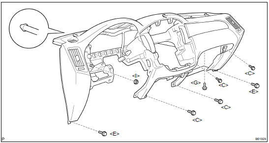
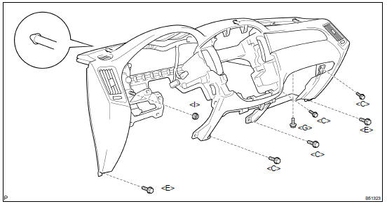
35. REMOVE INSTRUMENT PANEL SAFETY PAD SUB-ASSY W/PASSENGER AIR BAG ASSY
(a) Disconnect the connectors.
(b) Remove the 7 bolts <C> <E> <G> and the nut <I>.
(c) Disengage the 3 pins, then remove the instrument panel safety pad sub-assy.
36. REMOVE INSTRUMENT CLUSTER FINISH PANEL GARNISH NO.2
(a) Disengage the 4 clips, then remove the instrument cluster finish panel garnish No. 2.
37. REMOVE AUTOMATIC LIGHT CONTROL SENSOR
(a) Disconnect the connector.
(b) Remove the automatic light control sensor.
38. REMOVE COOLER (SOLAR SENSOR) THERMISTOR
(a) Disconnect the connector.
(b) Remove the cooler (solar sensor) thermistor.
NOTICE: Do not pry the cooler (solar sensor) thermistor off from the upper position.
39. REMOVE INSTRUMENT PANEL PIN NO.1
(a) Remove the 3 screws and the 3 instrument panel pin No.1.
40. REMOVE DEFROSTER NOZZLE ASSY
(a) Remove the 7 screws <A> and the defroster nozzle assy.
41. REMOVE SIDE DEFROSTER NOZZLE DUCT NO.1
(a) Remove the screw <A> and the defroster nozzle duct No. 1.
42. REMOVE SIDE DEFROSTER NOZZLE DUCT NO.2
(a) Remove the screw <A> and the side defroster nozzle duct No. 2.
43. REMOVE HEATER TO REGISTER DUCT NO.1
(a) Remove the clip.
(b) Remove the 3 screws <A> and the heater to register duct No. 1.
44. REMOVE HEATER TO REGISTER DUCT NO.4
(a) Remove the clip.
(b) Remove the 3 screws <A> and the heater to register duct No. 4.
45. REMOVE HEATER TO REGISTER CENTER SUB DUCT
(a) Remove the 4 screws <A> and the heater to register center sub duct.
46. REMOVE INSTRUMENT PANEL REGISTER ASSY LOWER NO.1
(a) Remove the 2 screws <A> and the instrument panel register assy lower No. 1.
47. REMOVE INSTRUMENT PANEL REGISTER ASSY NO.1
(a) Remove the 2 screws <A> and the instrument panel register assy No. 1.
48. REMOVE INSTRUMENT PANEL BRACKET SUB-ASSY CENTER
(a) Remove the 3 screws <A> and the instrument panel bracket sub-assy center.
49. REMOVE NAVIGATION ANTENNA ASSY (W/ NAVIGATION SYSTEM) (SEE PAGE 67-19 )
50. REMOVE INSTRUMENT PANEL WIRE
51. REMOVE INSTRUMENT PANEL PASSENGER AIR BAG ASSY (SEE PAGE 60-29 )
52. REMOVE INSTRUMENT PANEL SAFETY PAD SUB-ASSY
53. INSTALL INSTRUMENT PANEL PASSENGER AIR BAG ASSY (SEE PAGE 60-29 )
54. INSTALL INSTRUMENT PANEL SAFETY PAD SUB-ASSY W/PASSENGER AIR BAG ASSY
(a) Install the 7 bolts <C> <E> <G>, nut <I> with the instrument panel safety pad sub-assy.
Torque: Bolt <G>: 20 NVm (204 kgfVcm, 15 ftVlbf)
55. INSTALL FRONT SEAT ARMREST ASSY CENTER
56. CENTER SPIRAL CABLE (SEE PAGE 60-26 )
57. INSTALL STEERING WHEEL ASSY (SEE PAGE 50-8 )
58. INSPECT STEERING WHEEL CENTER POINT
59. INSTALL HORN BUTTON ASSY (SEE PAGE 60-17 )
60. CONNECT BATTERY NEGATIVE TERMINAL
61. INSPECT HORN BUTTON ASSY (SEE PAGE 60-1 1)
62. INSPECT SRS WARNING LIGHT (SEE PAGE 05-1207 )
 Instrument panel/meter
COMPONENTS
...
 Combination meter ASSY
OVERHAUL
HINT:
The installation is in the reverse order of the removal. However, when there is
a special point concerning
the installation, it is indicated.
1. REMOVE INSTRUMENT CLUSTER FINISH P ...
More about Toyota Highlander:
Starting & charging
SERVICE DATA
2AZ-FE
3MZ-FE
TORQUE SPECIFICATION
2AZ-FE
3MZ-FE
...
