Toyota Highlander Service Manual: Chain (2AZ-FE)
REPLACEMENT
1. REMOVE HOOD SUB-ASSY
2. REMOVE FRONT WHEEL RH
3. REMOVE ENGINE UNDER COVER NO.1
4. REMOVE FRONT FENDER SPLASH SHIELD FRONT RH
5. REMOVE FRONT FENDER APRON SEAL RH
6. DRAIN ENGINE OIL
(a) Install a new gasket and the drain plug after draining engine oil.
Torque: 25 NVm (255 kgfVcm, 18 ftVlbf)
7. REMOVE EXHAUST PIPE ASSY FRONT
8. REMOVE ENGINE MOVING CONTROL ROD W/BRACKET (See page 14-24 )
9. REMOVE ENGINE MOUNTING STAY NO.2 RH
10. REMOVE ENGINE MOUNTING BRACKET NO.2 RH
11. REMOVE FAN AND GENERATOR V BELT (See page 14-5 )
12. REMOVE ENGINE COVER SUB-ASSY NO.1
13. DISCONNECT ENGINE WIRE
14. REMOVE GENERATOR ASSY
15. REMOVE VANE PUMP ASSY (See page 51-8 )
NOTICE: Do not disconnect the hose.
16. REMOVE IGNITION COIL ASSY
17. DISCONNECT VENTILATION HOSE No.1
18. DISCONNECT VENTILATION HOSE NO.2
19. REMOVE ENGINE COVER SUB-ASSY NO.1
20. REMOVE CYLINDER HEAD COVER SUB-ASSY (Seepage 14-41 )
21. SET NO. 1 CYLINDER TO TDC/COMPRESSION (See page 14-6 )
22. REMOVE CRANKSHAFT PULLEY
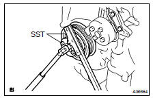
- Using SST, fix the pulley and loosen the bolt.
SST 09213-54015 (91651-60855), 09330-00021
- Using SST, remove the bolt and pulley.
SST 09950- 50013 (09951- 05010, 09952- 05010, 09953-05020, 09954-05021)
23. REMOVE CRANKSHAFT POSITION SENSOR
24. REMOVE OIL PAN SUB-ASSY (Seepage 14-41 )
25. REMOVE CHAIN TENSIONER ASSY NO.1 (See page 14-41 )
26. REMOVE V-RIBBED BELT TENSIONER ASSY (See page 14-24 )
27. INSTALL ENGINE HANGER NO.1
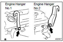
(a) Install the engine hanger No. 1 and No. 2 with the bolts as shown in the illustration.
Parts No.:
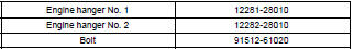
Torque: 38 NVm (387 kgfVcm, 30 ftVlbf)
28. REMOVE ENGINE MOUNTING INSULATOR
(a) Attach the engine chain hoist to the engine hangers.
CAUTION: Do not attempt to hang the engine by hooking the chain to any other part.
(b) Remove the bolt and disconnect the engine mounting insulator FR.
(c) Remove the bolt and disconnect the steering gear return hose clamp from the frame.
(d) Remove the 4 nuts from the engine mounting insulator RH.
(e) Raise the engine and remove the engine mounting insulator RH.
29. REMOVE ENGINE MOUNTING BRACKET RH
(a) Remove the 3 bolts and engine mounting bracket.
30. REMOVE TIMING CHAIN OR BELT COVER SUB-ASSSY
(a) Remove the stud bolt for the drive belt tensioner from the cylinder block.
(b) Remove the 14 bolts and 2 nuts.
(c) Pry out the timing chain cover with a screwdriver.
NOTICE: Be careful not to damage the contact surfaces of the timing chain cover, cylinder block and cylinder head.
31. REMOVE CRANKSHAFT POSITION SENSOR PLATE NO.1
32. REMOVE CHAIN TENSIONER SLIPPER
33. REMOVE CHAIN VIBRATION DAMPER NO.1
34. REMOVE CHAIN SUB-ASSY
35. REMOVE CRANKSHAFT TIMING GEAR OR SPROCKET
36. REMOVE NO.2 CHAIN SUB-ASSY
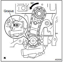
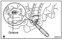
(a) Turn the crankshaft counterclockwise 90 , and align an adjusting hole of the oil pump driven sprocket with the groove of the oil pump.
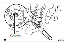
(b) Put a bar (f 4.0 mm (0.16 in.)) in the adjusting hole of the oil pump driven sprocket to temporarily lock the sprocket in position. Remove the nut.
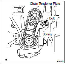
(c) Remove the bolt, chain tensioner plate and spring.
(d) Remove the chain tensioner, oil pump driven sprocket and chain.
37. INSTALL NO.2 CHAIN SUB-ASSY
(a) Set the crankshaft key into the left horizontal position.
(b) Turn the cutout of the drive shaft to the top.
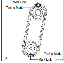
(c) Align the mark links (yellow colored links) with the timing marks of the sprocket as shown in the illustration.
(d) Insert the sprockets with chain to the crankshaft and oil pump shaft.
(e) Temporarily tighten the oil pump driven sprocket with the nut.
(f) Insert the damper spring into the adjusting hole, and install the chain tensioner plate with the nut.
Torque: 12 NVm (122 kgfVcm, 9.0 ftVlbf)
(g) Align the adjusting hole of the oil pump driven sprocket with the groove of the oil pump.
(h) Put a bar (f 4 mm (0.16 in.)) in the adjusting hole of the oil pump driven sprocket to temporarily lock the sprocket in position. Install the nut.
Torque: 30 NVm (306 kgfVcm, 22 ftVlbf)
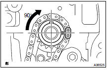
(i) Rotate the crankshaft counterclockwise 90 , and align the crankshaft key to the top.
38. INSTALL CHAIN VIBRATION DAMPER NO.1
Torque: 9.0 NVm (92 kgfVcm, 80 in.Vlbf)
39. INSTALL CHAIN SUB-ASSY
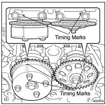
(a) Set the No.1 cylinder to TDC/compression.
- Align the timing marks of the camshaft timing sprockets and bearing caps (No. 1 and No. 2).
- Using the crankshaft pulley bolt, turn the crankshaft and set the set key on the crankshaft upward.
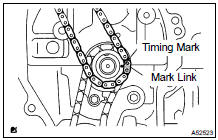
(b) Align the mark link (gold or orange colored link) with the timing mark of the crankshaft timing sprocket.
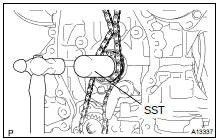
(c) Using SST, tap in the sprocket.
SST 09309-37010
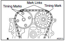
(d) Align the mark links (gold or yellow colored links) with the timing marks of the camshaft timing gear and camshaft timing sprocket. Install the chain.
40. INSTALL CHAIN TENSIONER SLIPPER Torque: 19 NVm (194 kgfVcm, 14 ftVlbf)
41. INSTALL CRANKSHAFT POSITION SENSOR PLATE NO.1 (See page 14-41 )
42. INSTALL TIMING CHAIN OR BELT COVER SUB-ASSSY
NOTICE:
- Remove any oil from the contact surface.
- Install the chain cover within 3 minutes after applying seal packing.
- Do not start the engine for at least 2 hours after installing.
(a) Remove any old packing (FIPG) material and be careful not to drop any oil on the contact surfaces of the timing chain cover, cylinder head and cylinder block.
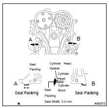
(b) Apply seal packing in a continuous bead (seal width: 2.0 mm (0.079 in.)) as shown in the illustration.
Seal packing: Part No. 08826-00080 or equivalent
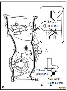
(c) Apply seal packing in a continuous bead (seal width: 3.0 to 4.0 mm (0.12 to 0.16 in.)) as shown in the illustration.
Seal packing: Part No. 08826-00080 or equivalent
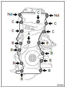
(d) Install the timing chain cover with the 14 bolts and 2 nuts.
Torque: 9.0 NVm (92 kgfVcm, 80 in.Vlbf) for bolt A 21 NVm (214 kgfVcm, 15 ftVlbf) for bolt B 43 NVm (438 kgfVcm, 32 ftVlbf) for bolt C 9.0 NVm (92 kgfVcm, 80 in.Vlbf) for nut
(e) Install the stud bolt to the drive belt tensioner.
Torque: 10 NVm (102 kgfVcm, 7 ftVlbf)
43. INSTALL CHAIN TENSIONER ASSY NO.1
44. INSTALL V-RIBBED BELT TENSIONER ASSY (See page 14-24 )
45. INSTALL ENGINE MOUNTING BRACKET RH
(a) Install the engine mounting bracket with the 3 bolts.
Torque: 54 NVm (551 kgfVcm, 40 ftVlbf)
46. INSTALL TRANSVERSE ENGINE ENGINE MOUNTING INSULATOR
(a) Raise the engine and install the engine mounting insulator RH.
(b) Install the engine mounting insulator RH with the 4 nuts.
Torque: 95 NVm (969 kgfVcm, 70 ftVlbf) for bolt A 87 NVm (887 kgfVcm, 64 ftVlbf) for bolt B
(c) Install the steering gear return hose clamp to the frame with the bolt.
Torque: 8.0 NVm (82 kgfVcm, 71 in.Vlbf)
(d) Install the engine mounting insulator FR with the bolt.
Torque: 87 NVm (887 kgfVcm, 64 in.Vlbf)
47. INSTALL OIL PAN SUB-ASSY (See page 14-41 )
48. INSTALL CRANKSHAFT POSITION SENSOR (See page 14-41 )
49. INSTALL CRANKSHAFT PULLEY
(a) Install the crankshaft pulley.
- Align the pulley set key with the key groove of the pulley, and side on the pulley.
- Using SST, install the pulley bolt.
SST 09213-54015 (91651-60855), 09330-00021 Torque: 180 NVm (1,835 kgfVcm, 133 ft lbf)
HINT: Apply a light coat of engine oil to the bolt threads and the area beneath the bolt heads that come in contact with the washers.
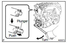
50. INSTALL CHAIN TENSIONER ASSY NO.1
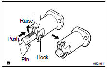
(a) Release the ratchet pawl, fully push in the plunger and apply the hook to the pin so that the plunger cannot spring out.

(b) Install a new gasket and the chain tensioner with the 2 nuts.
Torque: 9.0 NVm (92 kgfVcm, 80 in.Vlbf)
NOTICE: If the hook is released while inserting, apply the hook again, and insert the chain tensioner.
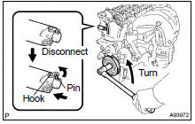
(c) Turn the crankshaft counterclockwise and check that the plunger knock pin is disconnected from the hook.
(d) Turn the crankshaft clockwise and check that the slipper is pushed by the plunger.
51. INSTALL CYLINDER HEAD COVER SUB-ASSY (See page 14-79 )
52. INSTALL IGNITION COIL ASSY Torque: 19 NVm (194 kgfVcm, 14 ftVlbf)
53. INSTALL VANE PUMP ASSY (See page 51-8 )
54. INSTALL GENERATOR ASSY (See page 19-16 )
55. INSTALL ENGINE WIRE
56. INSTALL FAN AND GENERATOR V BELT (See page 14-5 )
57. INSTALL ENGINE MOUNTING BRACKET NO.2 RH Torque: 52 NVm (531 kgfVcm, 38 ftVlbf)
58. INSTALL ENGINE MOUNTING STAY NO.2 RH Torque: 64 NVm (653 kgfVcm, 47 ftVlbf)
59. INSTALL ENGINE MOVING CONTROL ROD W/BRACKET (See page 14-24 )
60. INSTALL EXHAUST PIPE ASSY FRONT (See page 15-2 )
61. INSTALL FRONT WHEEL RH
62. INSTALL HOOD SUB-ASSY Torque: 13 NVm (133 kgfVcm, 10 ftVlbf)
63. ADD ENGINE OIL
64. CHECK FOR ENGINE OIL LEAKS
 Overhaul
1. REMOVE OIL FILTER SUB-ASSY
(a) Using SST, remove the oil filter.
SST 09228-06501
2. REMOVE OIL FILTER UNION
(a) Using a 12 mm hexagon wrench, remove the union.
3. REMOVE OIL FILLER CAP S ...
 Camshaft (2AZ-FE)
REPLACEMENT
1. REMOVE FRONT WHEEL RH
2. REMOVE FRONT FENDER SPLASH SHIELD FRONT RH
3. REMOVE FRONT FENDER APRON SEAL RH
4. REMOVE ENGINE COVER SUB-ASSY NO.1
5. REMOVE IGNITION COIL ASSY
6. REMOV ...
More about Toyota Highlander:
Replacement
1. REMOVE V (COOLER COMPRESSOR TO CRANKSHAFT PULLEY) BELT NO.1
(a) Loosen bolt A.
(b) Loosen bolt B.
(c) Loosen bolt C and remove the V belt.
2. INSTALL V (COOLER COMPRESSOR TO CRANKSHAFT PULLEY) BELT NO.1
(a) Temporarily install the V belt as illustrated.
3. ADJUST V (COOLER COMPRESSO ...
