Toyota Highlander Service Manual: Overhaul
1. REMOVE OIL FILTER SUB-ASSY
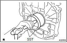
(a) Using SST, remove the oil filter.
SST 09228-06501
2. REMOVE OIL FILTER UNION
(a) Using a 12 mm hexagon wrench, remove the union.
3. REMOVE OIL FILLER CAP SUB-ASSY
4. REMOVE VENTILATION VALVE SUB-ASSY
5. REMOVE SPARK PLUG
6. REMOVE CYLINDER HEAD COVER SUB-ASSY
(a) Remove the 8 bolts, 2 nuts, and cylinder head cover.
7. REMOVE CYLINDER HEAD COVER GASKET
8. REMOVE CRANKSHAFT POSITION SENSOR
9. REMOVE CRANKSHAFT PULLEY
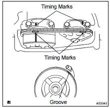
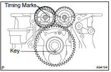
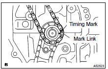
(a) Turn the crankshaft pulley and align its groove with timing mark 0 of the timing chain cover.
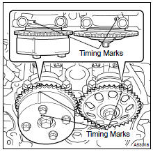
(b) Check that the timing marks of the camshaft timing sprockets are aligned with the timing marks of the No. 1 bearing cap, as shown in the illustration.
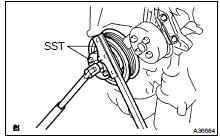
(c) Remove the crankshaft pulley.
- Using SST, fix the pulley and loosen the bolt.
SST 09213-54015 (91651-60855), 09330-00021
- Using SST, remove the bolt and pulley.
SST 09950- 50013 (09951- 05010, 09952- 05010, 09953-05020, 09954-05021)
10. REMOVE CHAIN TENSIONER ASSY NO.1
(a) Remove the 2 nuts, chain tensioner and gasket.
NOTICE: Do not turn the crankshaft without the chain tensioner.
11. REMOVE WATER PUMP PULLEY
(a) Using SST, remove the water pump pulley.
SST 09960-10010 (09962-01000, 09963-00700)
12. REMOVE WATER PUMP ASSY
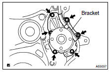
(a) Remove the 4 bolts, 2 nuts, bracket and water pump.
13. REMOVE OIL PAN DRAIN PLUG
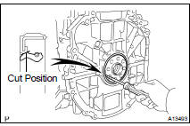
14. REMOVE OIL PAN SUB-ASSY
(a) Remove the 12 bolts and 2 nuts.
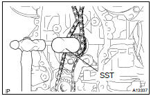
(b) Insert the blade of SST between the crankcase and oil pan. Cut off the applied sealer and remove the oil pan.
SST 09032-00100
NOTICE: Be careful not to damage the contact surface of the cylinder block and oil pan.
15. REMOVE TIMING CHAIN OR BELT COVER SUB-ASSY
(a) Remove the 14 bolts and 2 nuts.
(b) Remove the timing chain cover by prying between the timing chain cover and cylinder head or cylinder block with a screwdriver.
NOTICE: Be careful not to damage the contact surfaces of the timing chain cover, cylinder block and cylinder head.
16. REMOVE ENGINE REAR OIL SEAL
(a) Using a screwdriver and hammer, remove the oil seal.
17. REMOVE CRANKSHAFT POSITION SENSOR PLATE NO.1
18. REMOVE TIMING CHAIN GUIDE
19. REMOVE CHAIN TENSIONER SLIPPER
20. REMOVE CHAIN VIBRATION DAMPER NO.1
21. REMOVE CHAIN SUB-ASSY
22. REMOVE CRANKSHAFT TIMING GEAR OR SPROCKET
23. REMOVE NO.2 CHAIN SUB-ASSY
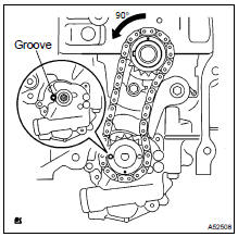
(a) Turn the crankshaft counterclockwise 90 , and align the adjusting hole of the oil pump driven sprocket with the groove of the oil pump.
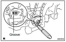
(b) Put a bar (f 4 mm (0.16 in.)) in the adjusting hole of the oil pump driven sprocket to temporarily lock the sprocket in position. then remove the nut.
(c) Remove the bolt, chain tensioner plate and spring.
(d) Remove the oil pump sprocket gear,driven sprocket and chain.
24. REMOVE OIL PUMP ASSY
(a) Remove the 3 bolts, oil pump and gasket.
25. REMOVE NO.2 CAMSHAFT (EXHAUST)
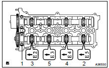
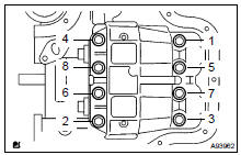
(a) Uniformly loosen and remove the No. 2 camshaft (exhaust)' s 10 bearing cap bolts in the sequence shown in the illustration. Then remove the 5 bearings.
(b) Remove the camshaft.
26. REMOVE CAMSHAFT (INTAKE)
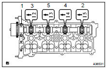
(a) Uniformly loosen and remove the camshaft (intake)'s 10 bearing cap bolts in the sequence shown in the illustration.
Then remove the 5 bearings.
(b) Remove the camshaft.
27. REMOVE CAMSHAFT BEARING NO.1
28. REMOVE CAMSHAFT TIMING GEAR OR SPROCKET
(a) Fix the camshaft with a vise and remove the camshaft timing sprocket.
NOTICE: Be careful not to damage the camshaft.
29. REMOVE CAMSHAFT TIMING GEAR ASSY
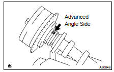
(a) Fix the camshaft with a vise, and make sure that the camshaft timing gear does not move.
(b) Cover all the oil ports with vinyl tape except the advanced angle side, as shown in the illustration.
(c) Using an air gun, apply about 150 kPa (1.5 kgf/cm2, 21 psi) of air pressure to the port on the advanced angle side.
CAUTION: Some oil spraying will occur. Contain the spray with a shop rag.
HINT: This operation releases the lock pin for the extreme retarded angle lock.
(d) Under the condition above, check that the camshaft timing gear can be turned by hand to the advanced angle side (counterclockwise), the direction of the arrow shown in the illustration.
Standard: Must turn
HINT: The camshaft timing gear will turn to the advanced angle side without applying force by hand depending on the force of the air pressure applied. Also, if applying pressure to the oil path is difficult as a result of air leakage from the port, the lock-pin may be difficult to release.
(e) Remove the fringe bolt from the camshaft timing gear.
NOTICE:
- Be sure not to remove the other 4 bolts.
- If planning to reuse the camshaft timing gear, release the straight pin lock first, and then install the gear.
30. REMOVE CAMSHAFT BEARING NO.2
31. REMOVE CAMSHAFT TIMING OIL CONTROL VALVE ASSY
32. REMOVE CYLINDER HEAD SUB-ASSY
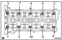
(a) Using a 10 mm bi-hexagon wrench, uniformly loosen the 10 bolts in the sequence shown in the illustration. Remove the 10 cylinder head bolts and plate washers.
NOTICE:
- Be careful not to drop the washers into the cylinder head.
- Head warpage or cracking could result from removing bolts in an incorrect order.
33. REMOVE CYLINDER HEAD GASKET
34. REMOVE CYLINDER BLOCK WATER DRAIN COCK SUB-ASSY
35. REMOVE OIL CONTROL VALVE FILTER
(a) Using a 6 mm socket hexagon wrench, remove the plug and filter.
36. REMOVE W/HEAD TAPER SCREW PLUG NO.1
37. INSPECT BALANCESHAFT THRUST CLEARANCE
(a) Using a dial indicator, measure the thrust clearance while moving the balanceshaft back and forth.
Standard thrust clearance: 0.050 to 0.090 mm (0.0020 to 0.0035 in.) Maximum thrust clearance: 0.090 mm (0.0035 in.)
If the thrust clearance is greater than the maximum, replace the balanceshaft housing and bearings. If necessary, replace the balance shaft.
38. INSPECT BALANCESHAFT OIL CLEARANCE
(a) Uniformly loosen and remove the 8 bolts in the sequence shown in the illustration.
NOTICE: Be careful not to damage the contact surfaces of the balanceshaft housing and crankcase.
HINT: Keep the lower bearing and balanceshaft housing together.
(b) Lift out the No. 1 and No. 2 balanceshafts.
HINT: Keep the upper bearing with the crankcase.
(c) Clean each bearing and journal.
(d) Check each bearing and journal for pitting and scratches.
If a bearing or journal is damaged, replace the bearings. If necessary, replace the balance shaft.
(e) Place the No. 1 and No. 2 balanceshafts on the crankcase.
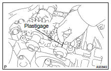
(f) Lay a strip of Plastigage across each journal, and install the balanceshaft housing.
(g) Apply a light coat of engine oil on the threads and under the heads of the balanceshaft housing bolts.
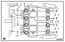
(h) Uniformly tighten the 8 bolts in the sequence shown in the illustration.
Torque: 22 NVm (220 kgfVcm, 16 ftVlbf)
HINT: The balanceshaft housing bolts are tightened in 2 progressive steps.
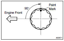
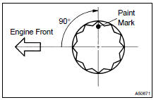
(i) Mark the front side of each balanceshaft housing bolt head with paint.
(j) Retighten the bolts 90 as shown in the illustration.
(k) Check that the paint marks are now at a 90 angle to the front.
(l) Remove the balanceshaft housing, and measure the Plastigage at its widest point.
Standard oil clearance: 0.004 to 0.031 mm (0.0002 to 0.0012 in.) Maximum oil clearance: 0.031 mm (0.0012 in.)
(m) Completely remove the Plastigage after the inspection.
If the clearance is greater than the maximum, replace the bearing.
If necessary, replace the balanceshaft.
If using a standard bearing, replace it with one of the same number.
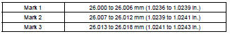
Balanceshaft housing journal bore diameter:
Balanceshaft journal diameter: 22.985 to 23.000 mm (0.9049 to 0.9055 in.)
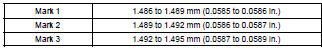
Standard bearing center wall thickness:
(n) Completely remove the Plastigage after the inspection.
39. REMOVE BALANCESHAFT
40. REMOVE BALANCESHAFT BEARING NO. 1
41. REMOVE ENGINE REAR OIL SEAL
(a) Using a knife, cut off the oil seal lip.
(b) Using a screwdriver with its tip taped, pry out the oil seal.
NOTICE: After the removal, check the crankshaft for damage. If it is damaged, smooth the surface with 400-grit sandpaper.
42. REMOVE STIFFENING CRANKCASE ASSY
(a) Uniformly loosen and remove the 11 bolts in the sequence shown in the illustration.
(b) Using a screwdriver, remove the crankcase by prying the portions between the crankcase and cylinder block.
NOTICE: Be careful not to damage the contact surfaces of the crankcase and cylinder block. (c) Remove the O-ring from the cylinder block.
43. INSPECT OIL PUMP DRIVE SPROCKET
(a) Wrap the chain around the drive gear.
(b) Using a vernier caliper, measure the sprocket diameter with the chain.
Minimum sprocket diameter (w/chain): 48.2 mm (1.898 in.)
NOTICE: The vernier caliper must contact the chain rollers for the measurement. If the diameter is less than the minimum, replace the chain and sprocket.
44. INSPECT OIL PUMP DRIVEN SPROCKET
(a) Wrap the chain around the drive shaft gear.
(b) Using a vernier caliper, measure the sprocket diameter with the chain.
Minimum gear diameter (w/chain): 48.2 mm (1.898 in.)
NOTICE: The vernier caliper must contact the chain rollers for the measurement. If the diameter is less than the minimum, replace the chain and sprocket.
45. INSPECT CRANKSHAFT TIMING GEAR OR SPROCKET

(a) Wrap the chain around the timing gear.
(b) Using a vernier caliper, measure the timing gear diameter with the chain.
Minimum gear diameter (w/ chain): 51.6 mm (2.031 in.)
NOTICE: The vernier caliper must contact the chain rollers for the measurement. If the diameter is less than the minimum, replace the chain and timing gear.
46. INSPECT CHAIN TENSIONER SLIPPER
(a) Measure the tensioner slipper wear.
Maximum wear: 1.0 mm (0.039 in.)
If the wear is greater than the maximum, replace the tensioner slipper
47. INSPECT CHAIN VIBRATION DAMPER NO.1
(a) Measure the vibration damper wear.
Maximum wear: 1.0 mm (0.039 in.)
If the wear is greater than the maximum, replace the vibration damper.
48. INSPECT CYLINDER HEAD SET BOLT
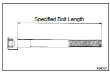
(a) Using a vernier caliper, measure the length of the head bolts from the seat to the end.
Standard bolt length: 161.3 to 162.7 mm (6.3503 to 6.4055 in.) Maximum bolt length: 164.2 mm (6.4646 in.)
If the length is greater than the maximum, replace the bolt.
49. INSPECT CHAIN TENSIONER ASSY NO.1
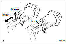
(a) Check that the plunger moves smoothly when the ratchet pawl is raised.
(b) Release the ratchet pawl and check that the plunger is locked in place by the ratchet pawl and does not move when pushed with your finger.
50. INSPECT CHAIN SUB-ASSY
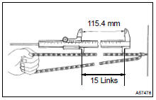
(a) Using a vernier caliper, measure the length of 15 links with the chain fully stretched.
Maximum chain elongation: 115.4 mm (4.543 in.)
NOTICE: Make the same measurements pulling at 3 or more places selected at random. Average the measurements.
If the elongation is greater than the maximum, replace the chain.
51. INSPECT CAMSHAFT TIMING GEAR OR SPROCKET
(a) Wrap the chain around the timing sprocket.
(b) Using a vernier caliper, measure the timing sprocket diameter with the chain.
Minimum sprocket diameter (w/chain): 97.3 mm (3.831 in.)
NOTICE: The vernier caliper must contact the chain rollers for the measurement. If the diameter is less than the minimum, replace the chain and timing gear.
52. INSPECT CAMSHAFT (INTAKE)
(a) Check the camshaft for runout.
- Place the camshaft on V-blocks.
- Using a dial indicator, measure the circle runout at the center journal.
Maximum circle runout: 0.03 mm (0.0012 in.) If the circle runout is greater than the maximum, replace the camshaft.
(b) Using a micrometer, measure the cam lobe height.
Standard cam lobe height: 46.495 to 46.595 mm (1.8305 to 1.8344 in.) Minimum cam lobe height: 46.385 mm (1.8262 in.)
If the cam lobe height is less than the minimum, replace the camshaft.
(c) Using a micrometer, measure the journal diameter.
No. 1 journal diameter: 35.971 to 35.985 mm (1.4162 to 1.4167 in.)
Other journal diameter: 22.959 to 22.975 mm (0.9039 to 0.9045 in.)
If the journal diameter is not as specified, check the oil clearance.
53. INSPECT NO.2 CAMSHAFT (EXHAUST)
(a) Check the camshaft for runout.
- Place the camshaft on V-blocks.
- Using a dial indicator, measure the circle runout at
the center journal.
Maximum circle runout: 0.03 mm (0.0012 in.)
If the circle runout is greater than the maximum, replace the camshaft.
(b) Using a micrometer, measure the cam lobe height.
Standard cam lobe height: 45.983 to 46.083 mm (1.8104 to 1.8143 in.) Minimum cam lobe height: 45.873 mm (1.8060 in.)
If the cam lobe height is less than the minimum, replace the camshaft.
(c) Using a micrometer, measure the journal diameter.
No. 1 journal diameter: 35.971 to 35.985 mm (1.4162 to 1.4167 in.)
Other journal diameter: 22.959 to 22.975 mm (0.9039 to 0.9045 in.)
If the journal diameter is not as specified, check the oil clearance.
54. INSTALL BALANCESHAFT BEARING NO.1
(a) Install the bearings in the crankcase and balanceshaft housing.
(b) Apply a light coat of engine oil on the bearings.
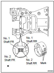
55. INSTALL BALANCESHAFT NO. 1 AND NO. 2
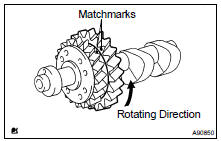
(a) Rotate the driven gear No. 1 of balanceshaft No. 1 for the rotating direction until it hits the stopper.
(b) Confirm that the matchmarks on driven gear No. 1 and No. 2 are matched.
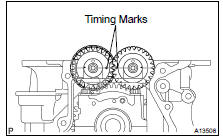
(c) Align the timing marks of the No. 1 and No. 2 balanceshafts as shown in the illustration.
(d) Place the No. 1 and No. 2 balance shafts on the crank case.
(e) Apply a light coat of engine oil under the heads of the balance shaft housing bolts.
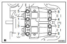
(f) Uniformly tighten the 8 bolts in the sequence shown in the illustration.
Torque: 22 NVm (224 kgfVcm, 16 ftVlbf)
HINT: The balanceshaft housing bolts are tightened in 2 progressive steps.
(g) Mark the front side of each balance shaft housing bolt head with paint.
(h) Retighten the bolts by 90 as shown in the illustration.
(i) Check that the painted marks are now at a 90 angle to the front.
56. INSTALL STIFFENING CRANKCASE ASSY
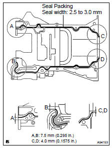
(a) Apply seal packing in a continuous bead (seal width: 2.5 to 3.0 mm (0.098 to 0.118 in.)) to the places shown in the illustration.
Seal packing: Part No. 08826-00080 or equivalent
NOTICE:
- Remove any oil from the contact surface.
- Install the crankcase within 3 minutes after applying seal packing.
- Do not start the engine for at least 2 hours after installing.
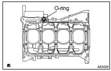
(b) Place a new O-ring on the cylinder block, as shown in the illustration.
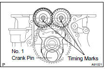
(c) With the No. 1 crank pin of the crankshaft placed at 6 o'clock, install the No. 1 and No. 2 balanceshaft and the adjusting hole as shown in the illustration.
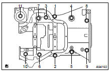
(d) Uniformly tighten the 11 bolts in the sequence shown in the illustration.
Torque: 33 NVm (337 kgfVcm, 24 ftVlbf)
(e) Confirm that the timing marks of the balanceshafts are matched when the key groove is placed at 6 o'clock, as shown in the illustration.
57. INSTALL ENGINE REAR OIL SEAL
(a) Apply MP grease to a new oil seal lip.
NOTICE: Keep the lip off the foreign materials.
(b) Using SST and a hammer, evenly tap the oil seal until its surface is flush with the rear oil seal retainer edge.
SST 09223-15030, 09950-70010 (09951-07100)
NOTICE: Wipe off extra grease on the crankshaft.
58. INSTALL W/HEAD TAPER SCREW PLUG NO.1
(a) Apply adhesive to the threads of the plug and install it.
Adhesive:
Part No. 08833-00070, THREE BOND 1324 or equivalent
Torque: 26 NVm (265 kgfVcm, 19 ftVlbf)
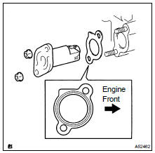
59. INSTALL OIL CONTROL VALVE FILTER FOR CAMSHAFT TIMING
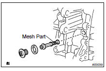
(a) Check that no foreign substance is on the mesh part of the filter.
(b) Using a 6 mm socket hexagon wrench, install a new gasket and the oil control valve filter with the screw plug.
Torque: 30 NVm (306 kgfVcm, 22 ftVlbf)
60. INSTALL CYLINDER BLOCK WATER DRAIN COCK SUB-ASSY
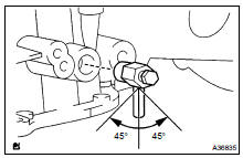
(a) Install the water drain cock within the range shown in the illustration.
Torque: 25 NVm (255 kgfVcm, 18 ftVlbf)
61. INSTALL CYLINDER HEAD GASKET
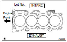
(a) Place a new gasket on the cylinder block surface with the Lot No. stamp upward.
NOTICE:
- Remove any oil from contact surface.
- Be careful of the installation direction.
- To avoid damage to the gasket, place the cylinder head on the gasket carefully.
62. INSTALL CYLINDER HEAD SUB-ASSY
HINT: The cylinder head bolts are tightened in 2 progressive steps.
(a) Apply a light coat of engine oil on the threads and under the heads of the cylinder head bolts.
(b) Install the 10 bolts and plate washers to the cylinder head.
NOTICE: Do not drop the washers into the cylinder head.
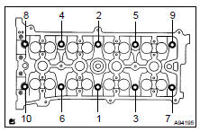
(c) Using a 10 mm bi-hexagon wrench, uniformly tighten the 10 bolts in the sequence shown in the illustration.
Torque: 79 NVm (806 kgfVcm, 58 ftVlbf)
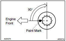
(d) Mark the front side of each cylinder head bolt with paint.
(e) Retighten the cylinder head bolts by 90 in the sequence shown in the illustration.
(f) Check that the painted marks are now at a 90 angle to the front.
63. INSTALL CAMSHAFT TIMING OIL CONTROL VALVE ASSY Torque: 9.0 NVm (92 kgfVcm, 80 in.Vlbf)
64. INSTALL CAMSHAFT BEARING NO.2
(a) Install the bearing to the camshaft.
NOTICE: Clean the contact surfaces of the bearing and the cylinder head. the surfaces should be free of dust and oils.
65. INSTALL CAMSHAFT TIMING GEAR ASSY
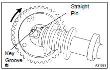
(a) Put the camshaft timing gear and the camshaft together with the straight pin and key groove.
(b) Turn the camshaft timing gear (as shown in the illustration) while pushing it lightly against the camshaft. Push further at the position where the pin enters the groove.
CAUTION: Be sure not to turn the camshaft timing gear to the retarded angle side (to the right angle). (c) Check that there is no clearance between the gear's fringe and the camshaft.
(d) Tighten the fringe bolt with the camshaft timing gear fixed.
Torque: 54 NVm (551 kgfVcm, 40 ftVlbf)
(e) Check that the camshaft timing gear can move to the retarded angle side (the right direction) and is locked at the extreme retarded angle position.
HINT:
- Apply a light coat of engine oil on the threads and under the heads of the bolt.
- Length of sprocket bolt excluding bolt head: 40 mm (1.57 in.)
66. INSTALL CAMSHAFT TIMING GEAR OR SPROCKET
(a) Fix the camshaft with a vise, and install the camshaft No.
2 timing gear.
Torque: 54 NVm (551 kgfVcm, 40 ftVlbf)
HINT:
- Apply a light coat of engine oil on the threads and under the heads of the bolt.
- Length of sprocket bolt excluding bolt head: 25 mm (0.98 in.)
67. INSTALL CAMSHAFT BEARING NO.1
68. INSTALL CAMSHAFT (INTAKE)
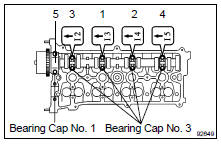
(a) Examine the front marks and numbers of the 5 bearing caps and install them. Then install the 10 bearing cap bolts. Uniformly tighten the bolts in the sequence shown in the illustration.
Torque:
30 NVm (306 kgfVcm, 22 ftVlbf) for bearing cap No. 1
9.0 NVm (92 kgfVcm, 80 in.Vlbf) for bearing cap No. 3
NOTICE:
- Tighten the bolts after deciding the position for the thrust direction of the camshaft by the bearing cap No. 1.
- Install the camshaft with its timing mark of the camshaft timing gear on top.
69. INSTALL NO.2 CAMSHAFT (EXHAUST)
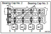
(a) Examine the front marks and numbers of the 5 bearing caps and install them. Then install the 10 bearing cap bolts. Uniformly tighten the bolts in the sequence shown in the illustration.
Torque: 30 NVm (306 kgfVcm, 22 ftVlbf) for bearing cap No. 2 9.0 NVm (92 kgfVcm, 80 in.Vlbf) for bearing cap No. 3
NOTICE:
- Tighten the bolts after deciding the position for the thrust direction of the camshaft by the bearing cap No. 2.
- Install the camshaft with its timing mark of the camshaft timing gear on top.
70. INSTALL OIL PUMP ASSY
(a) Install a new gasket and oil pump with the 3 bolts.
Torque: 19 NVm (194 kgfVcm, 14 ftVlbf)
71. INSTALL NO.2 CHAIN SUB-ASSY
(a) Set the crankshaft key into the left horizontal position.
(b) Turn the cutout of the drive shaft to the top.
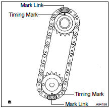
(c) Align the mark links (yellow colored links) with the timing marks of the sprocket as shown in the illustration.
(d) Insert the sprocket with chain to the crankshaft and oil pump shaft.
(e) Temporarily tighten the oil pump driven sprocket with the nut.
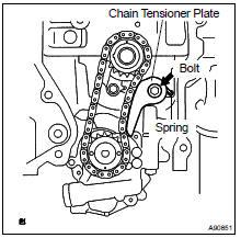
(f) Insert the damper spring into the adjusting hole, and install the chain tensioner plate by the bolt.
Torque: 12 NVm (122 kgfVcm, 9.0 ftVlbf)
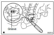
(g) Align the adjusting hole of the sprocket with the groove of the oil pump.
(h) Put a bar (f 4 mm (0.16 in.)) into the adjusting hole of the sprocket to temporarily lock the sprocket in position.
Install the nut.
Torque: 30 NVm (306 kgfVcm, 22 ftVlbf)
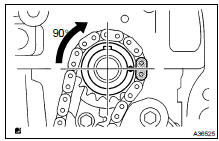
(i) Rotate the crankshaft clockwise 90 , and align the crankshaft key with the top.
72. INSTALL CRANKSHAFT TIMING GEAR OR SPROCKET
73. INSTALL CHAIN VIBRATION DAMPER NO.1
(a) Install the chain vibration damper with the 2 bolts.
Torque: 9.0 NVm (92 kgfVcm, 80 in.Vlbf)
74. INSTALL CHAIN SUB-ASSY
(a) Set the No. 1 cylinder to TDC/compression.
- Align the timing marks of the camshaft timing gear/ sprocket and bearing caps (No. 1 and No. 2).
- Using the crankshaft pulley bolt, turn the crankshaft and set the set key on the crankshaft upward.
(b) Align the mark link (blue or orange colored link) with the timing mark of the crankshaft timing sprocket.
(c) Using SST, tap in the sprocket.
SST 09309-37010
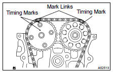
(d) Align the mark links (gold or yellow colored links) with the timing marks of the camshaft timing gear and camshaft timing sprocket. Then install the chain.
75. INSTALL CHAIN TENSIONER SLIPPER Torque: 19 NVm (194 kgfVcm, 14 ftVlbf)
76. INSTALL TIMING CHAIN GUIDE Torque: 9.0 NVm (92 kgfVcm, 80 in.Vlbf)
77. INSTALL CRANKSHAFT POSITION SENSOR PLATE NO.1
(a) Install the sensor plate with the F mark facing forward.
78. INSTALL TIMING GEAR CASE OR TIMING CHAIN CASE OIL SEAL
(a) Using SST, tap in a new oil seal until its surface is flush with the timing chain cover edge.
SST 09223-22010
(b) Apply a light coat of MP grease to the lip of the oil seal.
NOTICE: Keep the gap between the timing chain cover edge and the oil seal free of foreign matter.
79. INSTALL TIMING CHAIN OR BELT COVER SUB-ASSY
NOTICE:
- Remove any oil from the contact surface.
- Install the chain cover within 3 minutes after applying seal packing.
- Do not start the engine for at least 2 hours after installing.
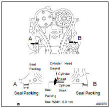
(a) Remove any old packing (FIPG) material and be careful not to drop any oil on the contact surfaces of the timing chain cover, cylinder head and cylinder block.
(b) Apply seal packing in a continuous bead (seal width: 2.0 mm (0.079 in.)) as shown in the illustration.
Seal packing: Part No. 08826-00080 or equivalent
(c) Apply seal packing in a continuous bead (seal width: 3.0 to 4.0 mm (0.12 to 0.16 in.)) as shown in the illustration.
Seal packing: Part No. 08826-00080 or equivalent
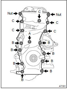
d) Install the timing chain cover with the 14 bolts and 2 nuts.
Torque:
9.0 NVm (92 kgfVcm, 80 in.Vlbf) for bolt A
21 NVm (214 kgfVcm, 15 ftVlbf) for bolt B
43NVm (438 kgfVcm, 32 ftVlbf) for bolt C
9.0 NVm (92 kgfVcm, 80 in.Vlbf) for nut
(e) Install the stud bolt to the drive belt tensioner.
Torque: 10 NVm (102 kgfVcm, 7 ftVlbf)
80. INSTALL OIL PAN SUB-ASSY
NOTICE:
- Remove any oil from the contact surface.
- Install the oil pan within 3 minutes after applying seal packing.
- Do not start the engine for at least 2 hours after installing.
(a) Remove any old packing (FIPG) material and be careful not to drop any oil on the contact surfaces of the cylinder block and oil pan.
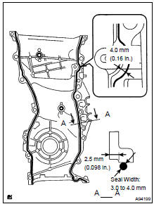
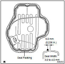
(b) Apply seal packing in a continuous bead (seal width: 3.0 to 4.0 mm (0.12 to 0.16 in.)) as shown in the illustration, and install the oil pan.
Seal packing: Part No. 08826-00080 or equivalent
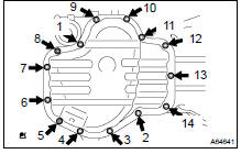
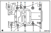
(c) Uniformly tighten the 12 bolts and 2 nuts in the sequence shown in the illustration.
Torque: 9.0 NVm (92 kgfVcm, 80 in.Vlbf)
81. INSTALL OIL PAN DRAIN PLUG
(a) Install a new gasket and the drain plug.
Torque: 25 NVm (255 kgfVcm, 18 ftVlbf)
82. INSTALL WATER PUMP ASSY
(a) Clean the contact surface of the cylinder block.
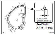
(b) Apply seal packing in a continuous bead (seal width: 2.2 to 2.5 mm (0.087 to 0.098 in.)) to the outside edge of the water pump.
Seal packing: Part No. 08826-00100 or equivalent
NOTICE:
- Remove any oil from the contact surface.
- Install the water pump within 5 minutes after applying seal packing.
- Do not start the engine for at least 2 hours after installing.
(c) Install the water pump with the 4 bolts and 2 nuts.
Torque: 9.0 NVm (92 kgfVcm, 80 in.Vlbf)
NOTICE: Tighten the outside bolts and nuts with the clamp.
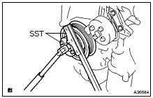
83. INSTALL WATER PUMP PULLEY
(a) Using SST, install the water pump pulley with the 4 bolts.
SST 09960-10010 (09962-01000, 09963-00700)
Torque: 26 NVm (265 kgfVcm, 19 ftVlbf)
84. INSTALL CRANKSHAFT POSITION SENSOR
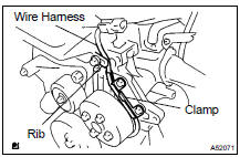
(a) Install the sensor with the 2 bolts.
Torque: 9.0 NVm (92 kgfVcm, 80 in.Vlbf) (b) Confirm that the wire harness of the sensor is placed as shown in the illustration.
85. INSTALL CRANKSHAFT PULLEY
(a) Install the pulley.
(b) Using SST,tighten the bolt.
SST 09213-54015 (91651-60855), 09330-00021
Torque: 180 NVm (1,835 kgfVcm, 133 ftVlbf)
HINT: Apply a light coat of engine oil to the bolt threads and the area beneath the bolt head that come in contact with the washer.
86. INSTALL CHAIN TENSIONER ASSY NO.1
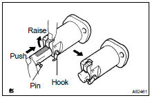
(a) Release the ratchet pawl, fully push in the plunger and apply the hook to the pin so that the plunger cannot spring out.
(b) Install a new gasket and the chain tensioner with the 2 nuts.
Torque: 9.0 NVm (92 kgfVcm, 80 in.Vlbf)
NOTICE: If the hook is released while inserting, apply the hook again, and insert the chain tensioner.
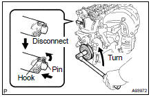
(c) Turn the crankshaft counterclockwise and check that the plunger knock pin is disconnected from the hook.
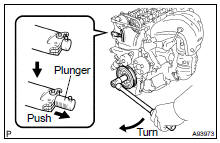
(d) Turn the crankshaft clockwise and check that the slipper is pushed by the plunger.
87. INSPECT VALVE CLEARANCE (See page 14-6 )
88. ADJUST VALVE CLEARANCE (See page 14-6 )
89. INSTALL CYLINDER HEAD COVER GASKET
(a) Install the gasket to the cylinder head cover.
90. INSTALL CYLINDER HEAD COVER SUB-ASSY
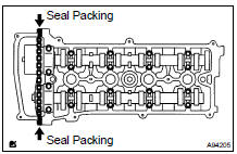
(a) Remove any old packing (FIPG) material.
(b) Apply seal packing to the 2 locations shown in the illustration.
Seal packing: Part No. 08826-00080 or equivalent
NOTICE:
- Remove any oil from the contact surface.
- Install the cylinder head cover within 5 minutes after applying seal packing.
- Do not apply engine oil for at least 2 hours after installing.
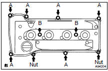
(c) Install the cylinder head cover with the 8 bolts and 2 nuts.
Torque:
11 NVm (112 kgfVcm, 8 ftVlbf) for nut
11 NVm (112 kgfVcm, 8 ftVlbf) for bolt A
14 NVm (143 kgfVcm, 10 ftVlbf) for bolt B
91. INSTALL SPARK PLUG Torque: 19 NVm (194 kgfVcm, 14 ftVlbf)
92. INSTALL VENTILATION VALVE SUB-ASSY
(a) Apply adhesive on the threads of the ventilation valve.
Torque: 19 NVm (194 kgfVcm, 14 ftVlbf)
Adhesive: Part No. 08833-00070 THREE BOND 1324 or equivalent
93. INSTALL OIL FILLER CAP SUB-ASSY
94. INSTALL OIL FILTER UNION
(a) Using a 12 mm hexagon wrench, install the oil filter union.
Torque: 30 NVm (306 kgfVcm, 22 ftVlbf)
95. INSTALL OIL FILTER SUB-ASSY
(a) Check and clean the oil filter installation surface.
(b) Apply clean engine oil to the gasket of a new oil filter.
(c) Lightly screw the oil filter into place, and tighten it until the gasket contacts the seat.
(d) Using SST, tighten it an additional 3/4 turn.
SST 09228-06501
 Replacement
1. WORK FOR PREVENTING GASOLINE FROM SPILLING OUT (See page 11-1 )
2. REMOVE FRONT WHEEL
3. REMOVE ENGINE UNDER COVER NO.1
4. REMOVE FRONT FENDER SPLASH SHIELD FRONT RH
5. REMOVE FRONT FENDER SPLA ...
 Chain (2AZ-FE)
REPLACEMENT
1. REMOVE HOOD SUB-ASSY
2. REMOVE FRONT WHEEL RH
3. REMOVE ENGINE UNDER COVER NO.1
4. REMOVE FRONT FENDER SPLASH SHIELD FRONT RH
5. REMOVE FRONT FENDER APRON SEAL RH
6. DRAIN ENGINE ...
More about Toyota Highlander:
Inspection
1. INSPECT WATER PUMP ASSY
(a) Visually check the drain hole for coolant leakage.
(b) Turn the pulley, and check that the water pump bearing
moves smoothly and noiselessly.
If the bearing moves roughly or noisily, replace the water pump
assy.
(c) Visually check the air holes for coolan ...
