Toyota Highlander Service Manual: Automatic transaxle ASSY (U151E/U151F)
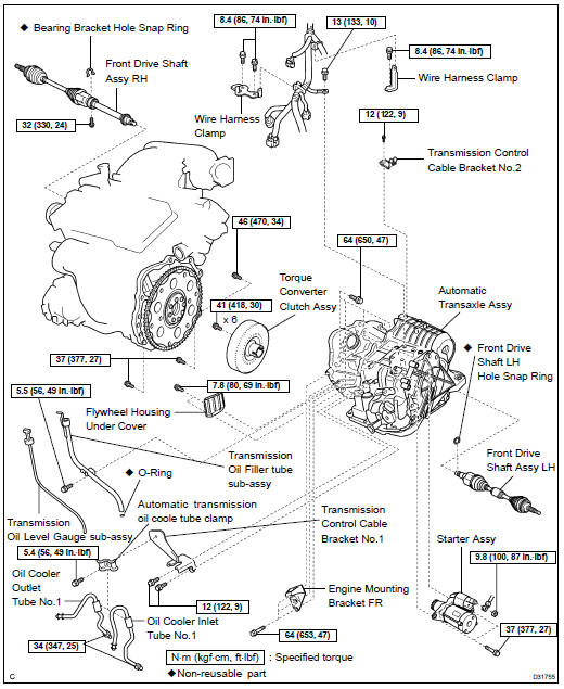
COMPONENTS
REPLACEMENT
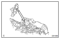
1. REMOVE ENGINE ASSEMBLY WITH TRANSAXLE (SEE PAGE 14-149 )
2. REMOVE FRONT DRIVE SHAFT ASSY LH (SEE PAGE 30-21 )
SST 09520-01010, 09520-24010 (09520-32040)
3. REMOVE FRONT DRIVE SHAFT ASSY RH (2WD DRIVE TYPE) (SEE PAGE 30-21 )
4. REMOVE FRONT DRIVE SHAFT ASSY RH (4WD DRIVE TYPE) (SEE PAGE 30-21 )
SST 09520-01010, 09520-24010 (09520-32040)
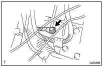
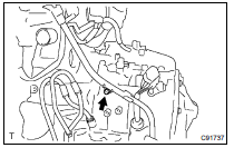
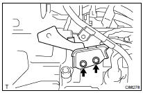
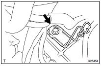
5. REMOVE TRANSMISSION CONTROL CABLE BRACKET NO.2
(a) Remove the bolt and transmission control cable bracket No.2.
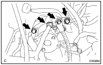
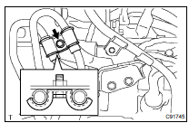
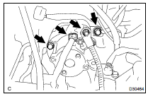
6. REMOVE WIRE HARNESS CLAMP
(a) Disconnect the wire harnesses from the clamps.
(b) Remove the 3 bolts and 2 clamps.
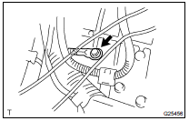
7. DISCONNECT WIRE HARNESS
(a) Remove the bolt and wire harness.
8. REMOVE STARTER ASSY
(a) Remove the nut and disconnect the starter wire.
(b) Disconnect the connector.
(c) Remove the 2 bolts and starter assy.
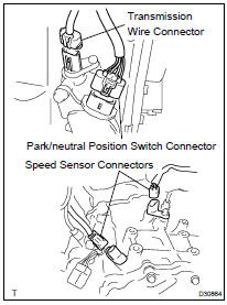
9. DISCONNECT CONNECTOR
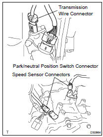
(a) Disconnect the transmission wire connector.
(b) Disconnect the park/neutral position switch connector.
(c) Disconnect the 2 speed sensor connectors.
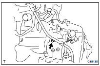
10. REMOVE TRANSMISSION CONTROL CABLE BRACKET NO.1
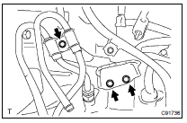
(a) Remove the bolt and automatic transmission oil cooler tube clamp.
(b) Remove the 2 bolts and transmission control cable bracket No.1.
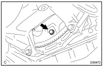
11. REMOVE TRANSMISSION OIL FILLER TUBE SUB-ASSY
(a) Remove the transmission oil level gauge sub-assy.
(b) Remove the bolt and transmission oil filler tube sub-assy.
(c) Remove the O-ring from the transmission oil filler tube sub-assy .
(d) Disconnect the breather hose from the wire harness bracket.
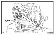
12. REMOVE OIL COOLER INLET TUBE NO.1
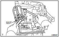
(a) Using SST and a spanner, disconnect the oil cooler inlet tube No.1.
SST 09023-12701
13. REMOVE OIL COOLER OUTLET TUBE NO.1
(a) Using SST and a spanner, disconnect the oil cooler outlet tube No.1.
SST 09023-12701
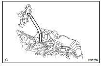
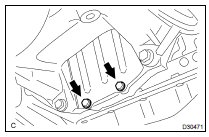
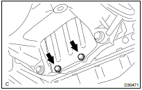
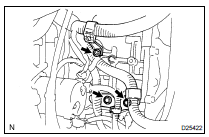
14. REMOVE ENGINE MOUNTING BRACKET FR
(a) Remove the 3 bolts and engine mounting bracket FR.
15. REMOVE AUTOMATIC TRANSAXLE ASSY
(a) Remove the 2 bolts and flywheel housing under cover.
(b) Turn the crankshaft to gain access and remove the 6 bolts while holding the crankshaft pulley bolt with a wrench.
HINT: There will be one green colored bolt.
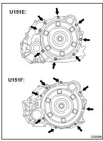
(c) Remove the 8 bolts.
(d) Separate and remove the automatic transaxle.
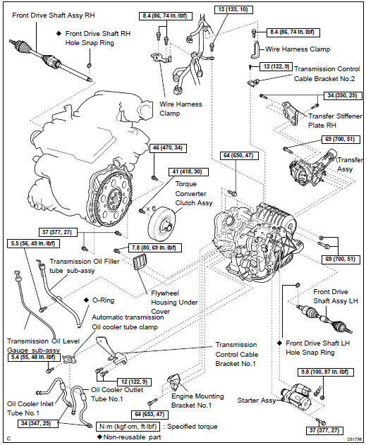
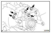
16. REMOVE TRANSFER STIFFENER PLATE RH (4WD DRIVE TYPE)
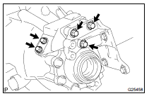
(a) Remove the 5 bolts and transfer stiffener plate RH.
17. REMOVE TRANSFER ASSY (4WD DRIVE TYPE) (SEE PAGE 31-9 )
18. REMOVE TORQUE CONVERTER CLUTCH ASSY
19. INSPECT TORQUE CONVERTER CLUTCH ASSY (SEE PAGE 40-2 )
SST 09350-32014 (09351-32010, 09351-32020)
20. INSTALL TORQUE CONVERTER CLUTCH ASSY
(a) Install the torque converter clutch to the automatic transaxle.
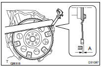
(b) Using vernier calipers and a straight edge, measure the dimension "A" between the transaxle fitting part of the engine and the converter fitting part of the drive plate.
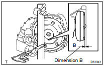
(c) Using vernier calipers and a straight edge, measure the dimension "B" shown in the illustration and check that "B" is greater than "A", previously measured. See step 20 (b).
Standard: A + 1 mm or more
NOTICE: Remember to minus the thickness of the straight edge.
21. INSTALL TRANSFER ASSY (4WD DRIVE TYPE) (SEE PAGE 31-9 )
22. INSTALL AUTOMATIC TRANSMISSION W/TRANSFER
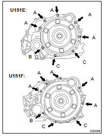
(a) Install the automatic transaxle w/ transfer with the 8 bolts to the engine.
Torque: Bolts A: 64 NVm (650 kgfVcm, 47 ftVlbf) Bolt B: 46 NVm (470 kgfVcm, 34 ftVlbf) Bolts C: 37 NVm (377 kgfVcm, 27 ftVlbf)
(b) Apply a few drops of adhesive to each of 2 threads on the tip of the 6 torque converter clutch mounting bolts.
Adhesive: Part No. 08833-00070, THREE BOND 1324 or equivalent
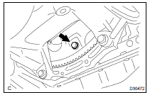
(c) Install the 6 torque converter clutch mounting bolts.
Torque: 41 NVm (418 kgfVcm, 30 ftVlbf)
HINT: First install the green colored bolt and then the remaining 5 bolts.
(d) Install the flywheel housing under cover to the automatic transaxle with the 2 bolts.
Torque: 7.8 NVm (80 kgfVcm, 69 inVlbf)
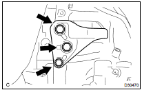
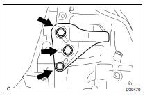
23. INSTALL TRANSFER STIFFENER PLATE RH (4WD DRIVE TYPE)
(a) Install the transfer stiffener plate RH with 5 bolts to the transfer and engine mounting bracket RR.
Torque: 34 NVm (350 kgfVcm, 25 ftVlbf)
24. INSTALL ENGINE MOUNTING BRACKET FR
(a) Install the engine mounting bracket FR and 3 bolts to the automatic transaxle.
Torque: 64 NVm (653 kgfVcm, 47 ftVlbf)
25. INSTALL TRANSMISSION OIL FILLER TUBE SUB-ASSY
(a) Coat a new O-ring with ATF, and install it to the transmission oil filler tube sub-assy.
(b) Install the transmission oil filler tube sub-assy and bolt to the automatic transaxle.
Torque: 5.5 NVm (56 kgfVcm, 49 in.Vlbf)
(c) Install the transmission oil level gauge sub-assy.
NOTICE:
- The breather hose should be on the left side of the vehicle.
(d) Connect the breather hose to the wire harness bracket.
26. INSTALL TRANSMISSION CONTROL CABLE BRACKET NO.1
(a) Install the transmission control cable bracket No.1 and 2 bolts.
Torque: 12 NVm (122 kgfVcm, 9 ftVlbf)
27. INSTALL OIL COOLER INLET TUBE NO.1
(a) Temporarily install the oil cooler outlet tube No.1.
(b) Temporarily install the oil cooler inlet tube No.1.
(c) Install the automatic transmission oil cooler tube clamp and bolt.
Torque: 5.4 NVm (55 kgfVcm, 48 in.Vlbf)
HINT: Install the automatic transmission oil cooler tube clamp and bolt so that the oil cooler tube cushion is positioned as illustrated.
(d) Using SST and a spanner, tighten the oil cooler inlet tube No.1.
SST 09023-12701
Torque: 34 NVm (347 kgfVcm, 25 ftVlbf)
28. INSTALL OIL COOLER OUTLET TUBE NO.1
(a) Using SST and a spanner, tighten the oil cooler outlet tube No.1.
Torque: 34 NVm (347 kgfVcm, 25 ftVlbf)
SST 09023-12701
29. CONNECT CONNECTOR
(a) Connect the transmission wire connector.
(b) Connect the park/neutral position switch connector.
(c) Connect the 2 speed sensor connectors
30. INSTALL STARTER ASSY
(a) Install the starter assy and 2 bolts.
Torque: 37 NVm (377 kgfVcm, 27 ftVlbf)
(b) Connect the connector.
(c) Install the starter wire and nut.
Torque: 9.8 NVm (100 kgfVcm, 87 in.Vlbf)
31. INSTALL WIRE HARNESS
(a) Install the wire harness and bolt.
Torque: 13 NVm (130 kgfVcm, 9 ftVlbf)
32. INSTALL WIRE HARNESS CLAMP
(a) Install the 2 clamps and 3 bolts.
Torque: 8.4 NVm (86 kgfVcm, 74 in.Vlbf)
(b) Connect the wire harnesses to the clamps.
33. INSTALL TRANSMISSION CONTROL CABLE BRACKET NO.2
(a) Install the transmission control cable bracket No.2 with the bolt.
Torque: 12 NVm (122 kgfVcm, 9 ftVlbf)
34. INSTALL FRONT DRIVE SHAFT ASSY LH (SEE PAGE 30-21 )
35. INSTALL FRONT DRIVE SHAFT ASSY RH (2WD DRIVE TYPE) (SEE PAGE 30-21 )
36. INSTALL FRONT DRIVE SHAFT ASSY RH (4WD DRIVE TYPE) (SEE PAGE 30-21 )
37. INSTALL ENGINE ASSEMBLY WITH TRANSAXLE (SEE PAGE 14-149 )
38. RESET MEMORY (SEE PAGE 05-1005 )
39. PERFORM INITIALIZATION (SEE PAGE 01-4 )
 Automatic transaxle ASSY (U241E/U140F)
REPLACEMENT
1. REMOVE ENGINE ASSY W/ TRANSAXLE (SEE PAGE 14-24 )
2. REMOVE FRONT DRIVE SHAFT ASSY RH (SEE PAGE 30-21 )
3. REMOVE FRONT DRIVE SHAFT ASSY LH (SEE PAGE 30-21 )
4. REMOVE TRANSVERSE EN ...
 Torque converter clutch and drive plate (ATM)
INSPECTION
1. INSPECT TORQUE CONVERTER CLUTCH ASSY
(a) Inspect the one-way clutch.
Install SST into the inner race of the one- way
clutch.
SST 09350-32014 (09351-32010)
...
More about Toyota Highlander:
Changing engine switch modes
Modes can be changed by pressing the engine switch with brake
pedal released. (The mode changes each time the switch is pressed.)
Off*
the emergency flashers can be
used.
The multi-information display will
not be displayed.
Accessory mode
some electrical components such
as the pow ...
