Toyota Highlander Service Manual: Valve clearance (3MZ-FE)
ADJUSTMENT
1. DRAIN ENGINE COOLANT (See page 16-26 )
2. REMOVE FR WIPER ARM LH (See page 66-7 )
3. REMOVE FR WIPER ARM RH (See page 66-7 )
4. REMOVE COWL TOP VENTILATOR LOUVER SUB-ASSY (See page 66-7 )
5. REMOVE WINDSHIELD WIPER LINK ASSY (See page 66-7 )
6. REMOVE COWL PANEL SUB-ASSY
7. REMOVE FRONT FENDER APRON SEAL RH
8. REMOVE FRONT SUSPENSION BRACE SUB-ASSY UPPER CENTER
9. REMOVE V-BANK COVER SUB-ASSY (See page 14-149 )
10. REMOVE AIR CLEANER CAP SUB-ASSY
11. REMOVE EMISSION CONTROL VALVE SET (See page 14-149 )
12. REMOVE INTAKE AIR SURGE TANK (See page 14-149 )
13. REMOVE RADIATOR HOSE INLET
14. REMOVE IGNITION COIL ASSY
15. REMOVE CYLINDER HEAD COVER SUB-ASSY (See page 14-173 )
16. REMOVE CYLINDER HEAD COVER SUB-ASSY LH (See page 14-173 )
17. INSPECT VALVE CLEARANCE
(a) Turn the crankshaft pulley, and align the timing notch with timing mark 0 of the No. 1 timing belt cover.
(b) Check that the valve lifters on the No. 1 (IN and EX) are both loose.
If not, turn the crankshaft 1 revolution (360 ) and align the mark as above.
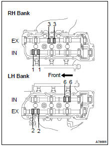
(c) Check the valves indicated in the illustration on the left.
- Using a feeler gauge, measure the clearance between the valve lifter and camshaft.
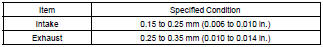
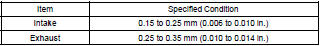
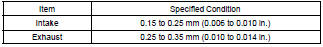
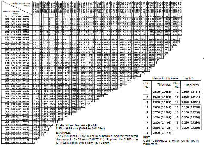
Valve clearance (Cold):
- Record valve clearance measurements that are out of the specified range. These measurements will be used later to determine the size of the adjustment shim to be installed
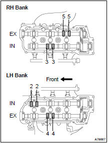
(d) Turn the crankshaft 2/3 of a revolution (240 ), and check the valves indicated in the illustration on the left.
- Using a feeler gauge, measure the clearance between the valve lifter and camshaft.
Valve clearance (Cold):
- Record valve clearance measurements that are out of the specified range. These measurements will be used later to determine the size of the adjustment shim to be installed.
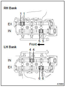
(e) Turn the crankshaft 2/3 of a revolution (240 ), and check the valves indicated in the illustration on the left.
- Using a feeler gauge, measure the clearance between the valve lifter and camshaft.
Valve clearance (Cold):
- Record valve clearance measurements that are out of the specified range. These measurements will be used later to determine the size of the adjustment shim to be installed.
18. ADJUST VALVE CLEARANCE
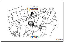
(a) Turn the camshaft so that the cam lobe faces upward.
(b) Turn the valve lifter with a screwdriver so that the notches are perpendicular to the camshaft.
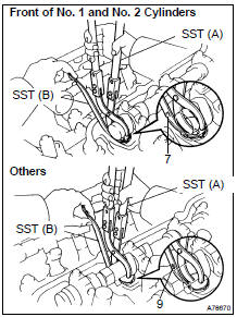
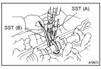
(c) Using SST (A), press down the valve lifter and place SST (B) between the camshaft and valve lifter. Remove SST (A).
SST 09248-55040 (09248-05410, 09248-05420)
HINT:
- Apply SST (B) at a slight angle on the side marked with "9" or "7" at the position shown in the illustration.
- When SST (B) is inserted too deeply, it will get pinched by the shim. To prevent it from being stuck, insert it gently from the intake side at a slight angle.
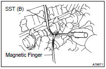
(d) Using a small screwdriver and magnetic finger, remove the adjusting shim.
(e) Using a micrometer, measure the thickness of the removed shim.
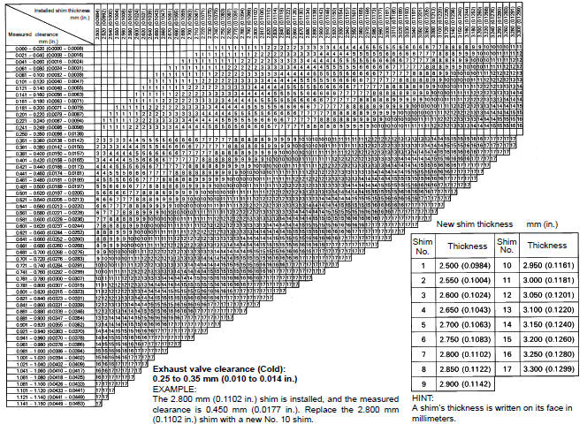
(f) Calculate the thickness of a new shim so that the valve clearance comes within the specified value
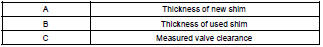
Specified value (Cold): Intake A = B + (C - 0.20 mm (0.0079 in.)) Exhaust A = B + (C - 0.30 mm (0.0118 in.))
(g) Select a new shim with a thickness as close as possible to the calculated values.
EXAMPLE (Intake): Measured valve clearance = 0.45 mm (0.0177 in.) 0.45 mm (0.0177 in.) - 0.20 mm (0.0079 in.) = 0.25 mm (0.0098 in.) (Measured - Specification = Excess clearance) Used shim measurement = 2.80 mm (0.1102 in.) 0.25 mm (0.0098 in.) + 2.80 mm (0.1102 in.) = 3.05 mm (0.1201 in.) (Excess clearance + Used shim = Ideal new shim) Closest new shim = 3.05 mm (0.1201 in.) Select No. 12 shim
HINT:
- Shims are available in 17 sizes in increments of 0.05 mm (0.0020 in.), from 2.50 mm (0.0984 in.) to 3.30 mm (0.1299 in.).
- Refer to adjusting shim selection chart on the following 2 pages.
Adjusting Shim Selection Chart (Intake)
Adjusting Shim Selection Chart (Exhaust)
(h) Place a new adjusting shim on the valve lifter with the imprinted number facing down.
(i) Press down the valve lifter with SST (A), and remove SST (B).
SST 09248-55040 (09248-05410, 09248-05420) (j) Recheck the valve clearance.
19. INSTALL CYLINDER HEAD COVER SUB-ASSY (See page 14-173 )
20. INSTALL CYLINDER HEAD COVER SUB-ASSY LH (See page 14-173 )
21. INSTALL IGNITION COIL ASSY Torque: 8.0 NVm (82 kgfVcm, 71 in.Vlbf)
22. INSTALL RADIATOR HOSE INLET
23. INSTALL INTAKE AIR SURGE TANK (See page 14-149 )
24. INSTALL EMISSION CONTROL VALVE SET (See page 14-149 )
25. INSTALL AIR CLEANER CAP SUB-ASSY
26. CONNECT VACUUM HOSES (See page 14-149 )
27. INSTALL V-BANK COVER SUB-ASSY (See page 14-149 )
28. INSTALL FRONT SUSPENSION BRACE SUB-ASSY UPPER CENTER Torque: 80 NVm (816 kgfVcm, 59 ftVlbf)
29. INSTALL COWL PANEL SUB-ASSY
30. INSTALL WINDSHIELD WIPER LINK ASSY (See page 66-7 )
31. INSTALL COWL TOP VENTILATOR LOUVER SUB-ASSY (See page 66-7 )
32. INSTALL FR WIPER ARM LH (See page 66-7 )
33. INSTALL FR WIPER ARM RH (See page 66-7 )
34. ADD ENGINE COOLANT (See page 16-26 )
35. CHECK FOR ENGINE COOLANT LEAKS (See page 16-20 )
 Drive belt (3MZ-FE)
REPLACEMENT
1. REMOVE FRONT WHEEL RH
2. REMOVE ENGINE UNDER COVER NO.1
3. REMOVE FRONT FENDER APRON SEAL RH
4. REMOVE V (COOLER COMPRESSOR TO CRANKSHAFT PULLEY) BELT NO.1
(a) Loosen bolts A a ...

More about Toyota Highlander:
If the vehicle battery is
discharged
The following procedures may be used to start the engine if the
vehicle’s battery is discharged.
You can also call your toyota dealer or a qualified repair shop.
If you have a set of jumper (or booster) cables and a second vehicle
with a 12-volt battery, you can jump start your vehicle by fo ...
