Toyota Highlander Service Manual: Steering column ASSY
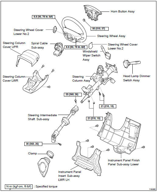
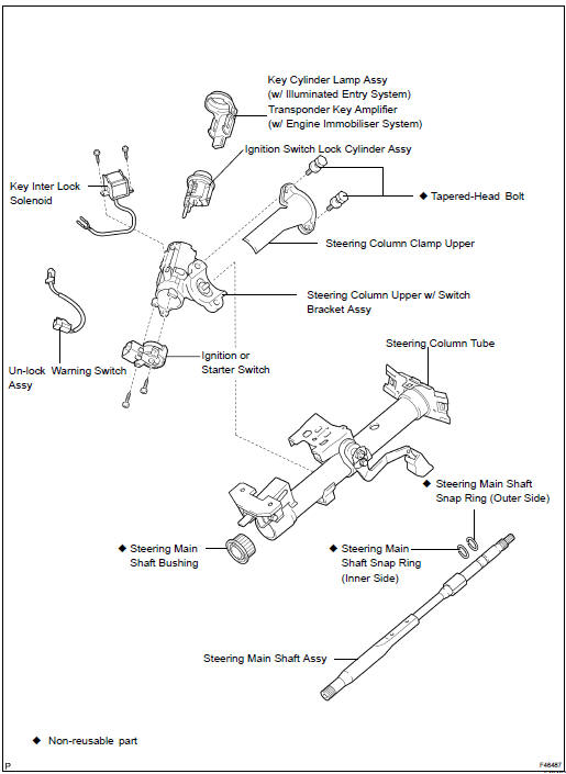
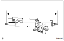
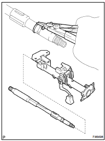
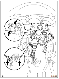
COMPONENTS
OVERHAUL
1. PRECAUTION (SEE PAGE 60-1 )
2. DISCONNECT BATTERY NEGATIVE TERMINAL (SEE PAGE 60-1 )
3. PLACE FRONT WHEELS FACING STRAIGHT AHEAD
4. REMOVE STEERING WHEEL COVER LOWER NO.2 (SEE PAGE 60-17 )
5. REMOVE HORN BUTTON ASSY (SEE PAGE 60-17 )
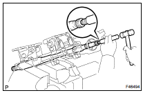
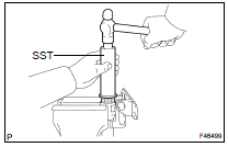
6. REMOVE STEERING WHEEL ASSY
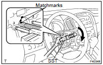
(a) Remove the steering wheel assy set nut.
(b) Place matchmarks on the steering wheel assy and main shaft assy.
(c) Using SST, remove the steering wheel assy.
SST 09950- 50013 (09951- 05010, 09952- 05010, 09953-05020, 09954-05021)
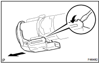
7. REMOVE STEERING COLUMN COVER LWR
(a) Remove the 3 screws and steering column cover LWR.
8. REMOVE STEERING COLUMN COVER UPR
9. REMOVE SPIRAL CABLE SUB-ASSY (SEE PAGE 60-26 )
10. REMOVE HEADLAMP DIMMER SWITCH ASSY (SEE PAGE 65-25 )
11. REMOVE WINDSHIELD WIPER SWITCH ASSY (SEE PAGE 66-16 )
12. REMOVE INSTRUMENT PANEL FINISH PANEL SUB-ASSY LOWER (SEE PAGE 71-10 )
13. REMOVE INSTRUMENT PNL INSERT SUB-ASSY LWR LH (SEE PAGE 71-10 )
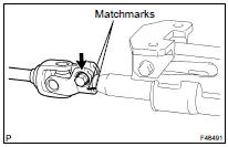
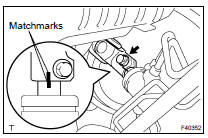
14. SEPARATE STEERING INTERMEDIATE SHAFT SUB-ASSY
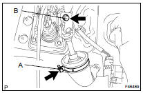
(a) Loosen the bolt A and remove the clamp from the steering intermediate shaft sub-assy.
(b) Loosen the bolt B.
(c) Place matchmarks on the steering intermediate shaft sub-assy and steering gear assy.
(d) Remove the bolt and separate the steering intermediate shaft sub-assy.
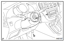
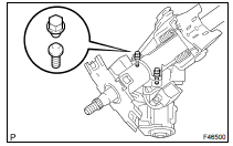
15. REMOVE STEERING COLUMN ASSY
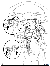
(a) Separate the connectors and wire harness clamps.
(b) Remove the 2 bolts, 2 nuts and steering column assy from the instrument panel reinforcement assy.
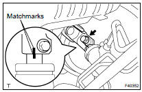
16. REMOVE STEERING INTERMEDIATE SHAFT SUB-ASSY
(a) Place matchmarks on the steering intermediate shaft sub-assy and steering shaft.
(b) Remove the bolt and steering intermediate shaft subassy.
17. REMOVE KEY CYLINDER LAMP ASSY (W/ ILLUMINATED ENTRY SYSTEM)
18. REMOVE TRANSPONDER KEY AMPLIFIER (W/ENGINE IMMOBILISER SYSTEM)
(a) Widen the claw hung on the upper bracket by approx. 1.0 mm (0.039 in.) using a screwdriver.
(b) Pull the transponder key amplifier toward the rear of the vehicle with the claw open.
NOTICE: Take care not to use excessive force to prevent the case from being damaged.
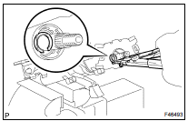
19. INSPECT STEERING MAIN SHAFT ASSY
(a) Measure the steering main shaft length.
Standard length: 504.5 1 mm (19.862 0.039 in.)
If the length is out of specification, replace the steering column assy with a new one.
20. REMOVE STEERING COLUMN UPPER W/SWITCH BRACKET ASSY
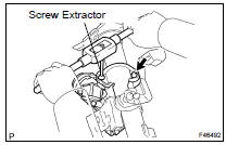
(a) Using a centering punch, mark the center of the 2 tapered- head bolts.
(b) Using a 3 to 4 mm (0.12 to 0.16 in.) drill, drill in to the 2 bolts.
(c) Using a screw extractor, remove the 2 bolts and steering column upper w/ switch bracket assy.
21. REMOVE STEERING COLUMN CLAMP UPPER
22. REMOVE STEERING MAIN SHAFT ASSY
(a) Using a snap ring expander, remove the steering main shaft snap ring (outer side).
(b) Using a brass bar and a hammer, remove the steering main shaft assy and steering main shaft bushing.
NOTICE: Be careful not to drop the steering main shaft assy.
(c) Using a snap ring expander, remove the steering main shaft snap ring (inner side).
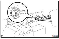
23. REMOVE IGNITION SWITCH LOCK CYLINDER ASSY
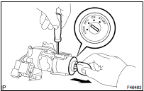
(a) Place the ignition switch lock cylinder assy at the ACC position.
(b) Push down the stop pin with a screwdriver, and pull out the cylinder assy.
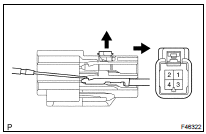
24. REMOVE UN-LOCK WARNING SWITCH ASSY
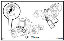
(a) Separate the un-lock warning switch assy connector from the ignition or starter switch assy.
(b) Remove the un-lock warning switch assy by pushing up the center part and releasing the 2 claws.
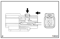
(c) Disengage the secondary locking device.
(d) Using a small screwdriver, disengage the locking lug of the terminals 2 and 4, and pull the terminals out from the un-lock warning switch assy rear side.
25. REMOVE KEY INTER LOCK SOLENOID
(a) Remove the 2 screws and solenoid from the steering column bracket assy.
26. REMOVE IGNITION OR STARTER SWITCH ASSY
(a) Remove the 2 screws and ignition or starter switch assy from the steering column bracket assy UPR.
27. INSTALL IGNITION OR STARTER SWITCH ASSY
(a) Install the ignition or starter switch assy to the steering column bracket assy UPR with the 2 screws.
28. INSTALL KEY INTER LOCK SOLENOID
(a) Install the solenoid to the steering column bracket assy with the 2 screws.
29. INSTALL UN-LOCK WARNING SWITCH ASSY
(a) Install the un-lock warning switch assy.
(b) Connect the terminals 2 and 4 of the un-lock warning switch assy connector.
(c) Connect the un-lock warning switch assy connector to the ignition or starter switch assy.
30. INSTALL IGNITION SWITCH LOCK CYLINDER ASSY
(a) Make sure the ignition switch lock cylinder assy at the ACC position.
(b) Install the ignition switch lock cylinder assy.
31. INSPECT STEERING LOCK OPERATION
(a) Check that the steering lock mechanism is activated when removing the key.
(b) Check that the steering lock mechanism is deactivated when inserting the key and turning it to ACC position.
HINT: If there is any abnormality, replace the ignition switch lock cylinder assy.
32. INSTALL STEERING MAIN SHAFT ASSY
(a) Using a snap ring expander, install a new steering main shaft snap ring (inner side) to the steering main shaft assy.
(b) Install the steering main shaft assy to the steering column tube.
(c) Using a snap ring expander, install a new steering main shaft snap ring (outer side) to the steering main shaft assy.
33. INSTALL STEERING MAIN SHAFT BUSH
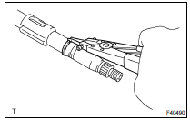
(a) Using SST and a hammer, install a new steering main shaft bushing.
SST 09608-06041
34. INSTALL STEERING COLUMN UPPER W/SWITCH BRACKET ASSY
(a) Temporarily install the steering column upper w/ switch bracket assy and steering column upper clamp with 2 new tapered-head bolts.
(b) Tighten the 2 tapered-head bolts until the bolt heads break off.
35. INSTALL KEY CYLINDER LAMP ASSY (W/ ILLUMINATED ENTRY SYSTEM)
36. INSTALL TRANSPONDER KEY AMPLIFIER (W/ENGINE IMMOBILISER SYSTEM)
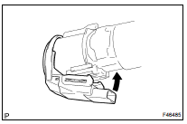
(a) Align the transponder key amplifier with the installation position of the upper bracket with the amplifier inclined.
(b) Push the transponder key amplifier up and connect it to the upper bracket.
NOTICE: Take care not to push the amplifier up with excessive force to prevent it from being damaged.
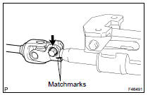
37. TEMPORARILY TIGHTEN STEERING INTERMEDIATE SHAFT SUB-ASSY
(a) Align the matchmarks on the steering intermediate shaft sub-assy and steering main shaft assy.
(b) Temporarily install the steering intermediate shaft subassy with the bolt.
38. INSTALL STEERING COLUMN ASSY
(a) Install the steering column assy with the 2 bolts and nuts.
Torque: 21 NVm (210 kgfVcm, 15 ftVlbf)
(b) Connect the connectors.
(c) Connect the wire harness clamps to the steering column tube.
39. CONNECT STEERING INTERMEDIATE SHAFT SUB-ASSY
(a) Align the matchmarks on the intermediate shaft sub-assy and steering gear assy.
(b) Install the bolt.
Torque: 35 NVm (360 kgfVcm, 26 ftVlbf)
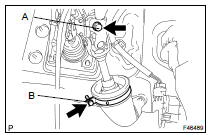
(c) Tighten the bolt A.
Torque: 35 NVm (360 kgfVcm, 26 ftVlbf)
(d) Connect the clamp to the steering intermediate shaft sub-assy and tighten the bolt B.
40. PLACE FRONT WHEELS FACING STRAIGHT AHEAD
41. INSPECT SPIRAL CABLE SUB-ASSY (SEE PAGE 60-26 )
42. INSTALL SPIRAL CABLE SUB-ASSY (SEE PAGE 60-26 )
43. CENTER SPIRAL CABLE (SEE PAGE 60-26 )
44. INSTALL STEERING COLUMN COVER UPR
45. INSTALL STEERING COLUMN COVER LWR
(a) Install the steering column cover LWR with the 3 screws.
46. INSTALL STEERING WHEEL ASSY
(a) Align the matchmarks on the steering wheel assy and steering main shaft assy.
(b) Install the steering wheel assy set nut.
Torque: 50 N*m (510 kgf*cm, 37 ft*lbf)
(c) Connect the connector.
47. INSTALL HORN BUTTON ASSY (SEE PAGE 60-17 )
48. CONNECT BATTERY NEGATIVE TERMINAL
49. INSPECT SRS WARNING LIGHT (SEE PAGE 05-1207 )
 Repair
1. STEERING OFF CENTER REPAIR PROCEDURE
(a) Inspect steering wheel off center.
Apply masking tape on the top center of the steering
wheel and steering column upper cover.
Driv ...
 Power steering
...
More about Toyota Highlander:
List of storage features
Auxiliary boxes
Open tray
Glove box
Bottle holders
Cup holders
Console box
Warning
Do not leave glasses, lighters or spray cans in the storage
spaces, as this
may cause the following when cabin temperature becomes high:
Glasses may be def ...
