Toyota Highlander Service Manual: Stabilizer bar front (4WD)
REPLACEMENT
HINT:
- COMPONENTS: See page 28-1 .
- Use the same procedures for the RH side and LH side.
- The procedures listed below are for the LH side.
1. REMOVE FRONT WHEEL
2. REMOVE FRONT STABILIZER LINK ASSY LH
(a) Remove the 2 nuts and the front stabilizer link assy LH.
HINT: If the ball joint turns together with the nut, use a hexagon wrench (6 mm) to hold the stud.
3. REMOVE FRONT STABILIZER LINK ASSY RH
HINT: Remove the RH side following the same procedures as with the LH side.
4. INSPECT FRONT STABILIZER LINK ASSY LH
(a) As shown in the illustration, flip the ball joint stud back and forth 5 times.
(b) Using a torque wrench and nut, turn the nut continuously at a rate of 2 to 4 seconds per turn and take the torque reading on the 5th turn.
Turning torque: 0.05 to 1.96 N*m (0.5 to 20 kgf*cm, 0.4 to 17.4 in.*lbf)
If the value is not within the specification, replace the front stabilizer link assy LH with a new one.
5. REMOVE EXHAUST PIPE SUB-ASSY FRONT NO.3 (3MZ-FE ENGINE TYPE)
6. REMOVE FRONT STABILIZER BRACKET NO.1 LH
(a) Remove the 2 bolts and front stabilizer bracket No.1 LH.
7. REMOVE FRONT STABILIZER BRACKET NO.1 RH
HINT: Remove the RH side following the same procedures as with the LH side.
8. REMOVE FRONT STABILIZER BRACKET NO.2 LH
(a) Remove the front stabilizer bracket No.2 LH from the stabilizer bar bush.
9. REMOVE FRONT STABILIZER BRACKET NO.2 RH
HINT: Remove the RH side following the same procedures with the LH side.
10. SEPARATE TIE ROD END SUB-ASSY LH (SEE PAGE 30-21 ) SST 09628-6201 1
11. SEPARATE TIE ROD END SUB-ASSY RH SST 09628-6201 1
HINT: Separate the RH side following the same procedures as with the LH side.
12. SEPARATE STEERING INTERMEDIATE SHAFT SUB-ASSY (SEE PAGE 51-28 )
13. DISCONNECT RETURN TUBE ASSY (SEE PAGE 51-28 ) SST 09023-12701
14. DISCONNECT PRESSURE FEED TUBE ASSY (SEE PAGE 51-28 ) SST 09023-12701
15. REMOVE POWER STEERING LINK ASSY (SEE PAGE 51-28 )
16. REMOVE FRONT STABILIZER BAR BUSH NO.1
(a) Remove the 2 bushes from the stabilizer.
17. REMOVE MANIFOLD STAY (3MZ-FE ENGINE TYPE) (SEE PAGE 15-5 )
18. REMOVE EXHAUST MANIFOLD HEAT INSULATOR NO.1 (3MZ-FE ENGINE TYPE) (SEE PAGE 15-5 )
19. REMOVE EXHAUST MANIFOLD CONVERTER SUB-ASSY (3MZ-FE ENGINE TYPE) (SEE PAGE 15-5 )
20. REMOVE STABILIZER BAR FRONT
(a) Remove the stabilizer bar front from the vehicle.
21. INSTALL STABILIZER BAR FRONT
(a) Install the stabilizer bar front from the vehicle.
22. INSTALL EXHAUST MANIFOLD CONVERTER SUB-ASSY (3MZ-FE ENGINE TYPE) (SEE PAGE 15-5 )
23. INSTALL EXHAUST MANIFOLD HEAT INSULATOR NO.1 (3MZ-FE ENGINE TYPE) (SEE PAGE 15-5 )
24. INSTALL MANIFOLD STAY (3MZ-FE ENGINE TYPE) (SEE PAGE 15-5 )
25. INSTALL FRONT STABILIZER BAR BUSH NO.1
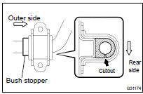
HINT:
- Install the bushing to the outer side of the bush stopper on the stabilizer bar.
- Place the cutout of the stabilizer bush facing the rear side as shown in the illustration.
26. INSTALL POWER STEERING LINK ASSY (SEE PAGE 51-28 )
27. INSTALL PRESSURE FEED TUBE ASSY (SEE PAGE 51-28 ) SST 09023-12701
28. INSTALL RETURN TUBE ASSY (SEE PAGE 51-28 ) SST 09023-12701
29. CONNECT STEERING INTERMEDIATE SHAFT SUB-ASSY (SEE PAGE 51-28 )
30. INSTALL TIE ROD END SUB-ASSY LH (SEE PAGE 30-21 )
31. INSTALL TIE ROD END SUB-ASSY RH
HINT: Install the RH side following the same procedures as with the LH side.
32. INSTALL FRONT STABILIZER BRACKET NO.2 LH
(a) Install the front stabilizer bracket No. 2 to the stabilizer bar bush No.1.
33. INSTALL FRONT STABILIZER BRACKET NO.2 RH
HINT: Install the RH side following the same procedures as with the LH side.
34. INSTALL FRONT STABILIZER BRACKET NO.1 LH
(a) Install the front stabilizer bracket No. 1 LH with the 2 bolts.
Torque: 16 NVm (163 kgfVcm, 12 ftVlbf)
35. INSTALL FRONT STABILIZER BRACKET NO.1 RH
HINT: Install the RH side following the same procedures as with the LH side.
36. INSTALL EXHAUST PIPE SUB-ASSY FRONT NO.3 (3MZ-FE ENGINE TYPE) (SEE PAGE 15-5 )
37. INSTALL FRONT STABILIZER LINK ASSY LH
(a) Install the front stabilizer link assy LH with the 2 nuts.
Torque: 74 NVm (755 kgfVcm, 55 ftVlbf)
HINT: If the ball joint turns together with the nut, use a hexagon wrench (6 mm) to hold the stud.
38. INSTALL FRONT STABILIZER LINK ASSY RH
HINT: Install the RH side following the same procedures as with the LH side.
39. INSTALL FRONT WHEEL Torque: 103 NVm (1,050 kgfVcm, 76 ftVlbf)
40. BLEED POWER STEERING FLUID (SEE PAGE 51-3 )
41. CHECK POWER STEERING FLUID LEAKAGE
42. INSPECT AND ADJUST STEERING WHEEL CENTER POINT
43. INSPECT AND ADJUST FRONT WHEEL ALIGNMENT (SEE PAGE 26-7 )
 Stabilizer bar front (FF)
REPLACEMENT
HINT:
COMPONENTS: See page 26-3 .
Use the same procedures for the RH side and LH side.
The procedures listed below are for the LH side.
1. REMOVE FRONT WHEEL
2. REMOVE FRONT S ...
 Rear suspension
...
More about Toyota Highlander:
On-vehicle inspection
1. INSPECT INTAKE AIR CONTROL SYSTEM
(a) Using a 3-way connector, connect a vacuum gauge to the
actuator hose.
(b) Connect the hand-held tester to the DLC3.
(c) Start the engine.
(d) On the hand-held tester, enter the ACTIVE TEST mode.
Standard:
...
