Toyota Highlander Service Manual: Replacement
1. REMOVE FRONT WHEEL
2. REMOVE ENGINE UNDER COVER NO.1
3. REMOVE FRONT FENDER APRON SEAL RH
4. DRAIN ENGINE OIL
(a) Install a new gasket after draining engine oil.
Torque: 45 NVm (459 kgfVcm, 33 ftVlbf)
5. REMOVE V (COOLER COMPRESSOR TO CRANKSHAFT PULLEY) BELT NO.1 (See page 14-125 )
6. REMOVE VANE PUMP V BELT (See page 14-125 )
7. REMOVE ENGINE MOVING CONTROL ROD (See page 14-149 )
8. REMOVE ENGINE MOUNTING STAY NO.2 RH
9. REMOVE GENERATOR BRACKET NO.2
10. REMOVE EXHAUST PIPE SUPPORT BRACKET NO.1
11. REMOVE EXHAUST PIPE ASSY FRONT (See page 15-5 )
12. SEPARATE COMPRESSOR AND MAGNETIC CLUTCH
(a) Remove the 2 bolts, nut and drive belt adjusting bar bracket.
(b) Remove the 2 nuts and the generator bracket adjusting bar together with the wire harness clamp bracket.
(c) Disconnect the compressor, magnetic clutch connector and wire harness clamp.
13. REMOVE COMPRESSOR MOUNTING BRACKET NO.1
(a) Remove the 2 bolts and mounting bracket.
14. REMOVE OIL LEVEL GAGE SUB-ASSY
15. REMOVE OIL LEVEL GAGE GUIDE
16. REMOVE ENGINE MOUNTING
(a) Remove the 4 nuts and bolt, and disconnect the engine mounting insulator FR.
NOTICE: Do not remove the engine mounting insulator.
(b) Remove the 4 bolts, nut and engine mounting bracket RH.
17. REMOVE CRANKSHAFT PULLEY (See page 14-173 )
18. REMOVE TIMING BELT NO.1 COVER (See page 14-173 )
19. REMOVE TIMING BELT NO.2 COVER (See page 14-173 )
20. REMOVE TIMING BELT GUIDE NO.2
21. REMOVE TIMING BELT (See page 14-173 )
22. REMOVE TIMING BELT IDLER SUB-ASSY NO.1
(a) Using a socket hexagon wrench 10, remove the pivot bolt, timing belt idler No. 1 and plate washer.
23. REMOVE TIMING BELT IDLER SUB-ASSY NO.2
24. REMOVE CAMSHAFT TIMING PULLEY (See page 14-173 )
25. REMOVE TIMING BELT NO.3 COVER (See page 14-173 )
26. REMOVE CRANKSHAFT TIMING PULLEY (See page 14-173 )
27. REMOVE OIL PAN SUB-ASSY NO.2 (See page 14-173 )
28. REMOVE OIL STRAINER SUB-ASSY
(a) Remove the bolt and 2 nuts, then remove the oil strainer and the gasket.
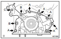
29. REMOVE OIL PAN SUB-ASSY
(a) Uniformly loosen and remove the 15 bolts and 2 nuts, as shown in the illustration.
(b) Using a screwdriver, remove the oil pan by prying between the cylinder block and the oil pan.
NOTICE: Be careful not to damage the contact surfaces of the oil pan and cylinder block.
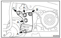
30. REMOVE OIL PUMP ASSY
(a) Remove the 9 bolts.
(b) Using a screwdriver, remove the oil pump by prying between the oil pump and the main bearing cap.
(c) Remove the O-ring.
31. INSTALL OIL PUMP ASSY
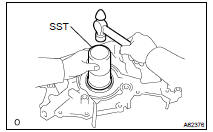
(a) Using SST and a hammer, install a new oil seal. Tap the surface of the SST with the hammer until the oil seal's surface is flush with the oil pump body edge.
SST 09223-00010
NOTICE:
- Be careful not to tap the oil seal at an angle.
- Keep the gap between the oil pump body edge and the oil seal free from contamination.
(b) Apply a small amount of MP grease to the oil seal lip.
(c) Remove any old seal packing material from the contact surface.
(d) Apply a light coat of engine oil to a new O-ring and place it on the cylinder block.
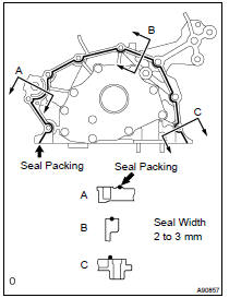
(e) Apply a continuous bead of seal packing (seal width: 2 to 3 mm (0.08 to 0.12 in.)) as shown in the illustration.
Seal packing: Part No. 08226-00080 or equivalent
NOTICE:
- Remove any oil from contact surface.
- Apply seal packing to the inner side of the bolt holes.
- Install the oil pump within 3 minutes after applying seal packing.
- Do not expose the seal to engine oil for at least 2 hours after installing the oil pump.
(f) Align the key of the oil pump drive gear with the key way located on the crankshaft, and slide the oil pump into place.
(g) Install the oil pump by tightening the 9 bolts uniformly.
Torque: 8.0 NVm (82 kgfVcm, 71 in.Vlbf) for bolt A 20 NVm (204 kgfVcm, 15 ftVlbf) for bolt B 43 NVm (438 kgfVcm, 32 ftVlbf) for bolt C
32. INSTALL OIL PAN SUB-ASSY (See page 14-173 )
33. INSTALL OIL STRAINER SUB-ASSY
(a) Install a new gasket and the oil strainer with the bolt and 2 nuts.
Torque: 8.0 NVm (82 kgfVcm, 71 in.Vlbf)
34. INSTALL OIL PAN SUB-ASSY NO.2 (See page 14-173 )
35. INSTALL CRANKSHAFT POSITION SENSOR Torque: 8.0 NVm (82 kgfVcm, 71 in.Vlbf)
36. INSTALL COMPRESSOR AND MAGNETIC CLUTCH (See page 14-149 )
37. INSTALL OIL LEVEL GAGE GUIDE
38. INSTALL OIL LEVEL GAGE SUB-ASSY
39. INSTALL TIMING BELT IDLER SUB-ASSY NO.1
(a) Using a socket hexagon wrench 10, install the plate washer and timing belt idler No. 1 with the pivot bolt.
Torque: 34 NVm (347 kgfVcm, 25 ftVlbf)
40. INSTALL TIMING BELT IDLER SUB-ASSY NO.2 Torque: 43 NVm (438 kgfVcm, 32 ftVlbf)
41. INSTALL TIMING BELT NO.3 COVER (See page 14-173 )
42. INSTALL CAMSHAFT TIMING PULLEY (See page 14-173 )
43. INSTALL TIMING BELT (See page 14-173 )
44. INSTALL CHAIN TENSIONER ASSY NO.1 (See page 14-173 )
45. INSTALL TIMING BELT GUIDE NO.2 (See page 14-41 )
46. INSTALL TIMING BELT NO.2 COVER
(a) Visually check for cracks and breaks on the gasket of the timing belt cover.
If there is a trace that water is entering at the visual check, replace the timing belt cover.
(b) Install the timing belt cover.
Torque: 9.0 NVm (92 kgfVcm, 80 in.Vlbf)
47. INSTALL TIMING BELT NO.1 COVER (See page 14-173 )
48. INSTALL ENGINE MOUNTING
(a) Install the engine mounting bracket RH with the 4 bolts and nut.
Torque: 54 NVm (551 kgfVcm, 40 ftVlbf) for bolt A 54 NVm (551 kgfVcm, 40 ftVlbf) for nut B 43 NVm (438 kgfVcm, 32 ftVlbf) for bolt C
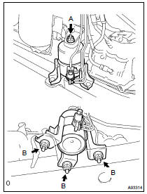
(b) Install the engine mounting insulator RH with the 4 nuts.
Torque: 95 NVm (969 kgfVcm, 70 ftVlbf) for nut A 87 NVm (887 kgfVcm, 64 ftVlbf) for nut B
HINT: First, loosely install the nut labeled (A) with your hand. Then use a wrench to install the 3 nuts labeled (B). Finally, use a wrench to tighten nut (A).
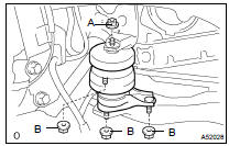
(c) Install the engine mounting insulator FR with the nut.
Torque: 87 NVm (887 kgfVcm, 64 ftVlbf) for nut A 52 NVm (530 kgfVcm, 38 ftVlbf) for nut B
49. INSTALL CRANKSHAFT PULLEY (See page 14-173 )
50. INSTALL GENERATOR BRACKET NO.1
(a) Visually check for cracks and breaks on the gasket of the timing belt cover.
If there is a trace that water is entering at the visual check, replace the timing belt cover.
(b) Install the timing belt cover.
Torque: 9.0 NVm (92 kgfVcm, 80 in.Vlbf)
51. INSTALL COMPRESSOR AND MAGNETIC CLUTCH
(a) Install the compressor with the 3 bolts.
Torque: 25 NVm (255 kgfVcm, 18 ftVlbf) (b) Install the adjusting bar bracket with the bolt and nut.
Torque:25 NVm (255 kgfVcm, 18 ftVlbf) for bolt
52. INSTALL ENGINE MOUNTING STAY NO.2 RH Torque: 64 NVm (653 kgfVcm, 47 ftVlbf)
53. INSTALL ENGINE MOVING CONTROL ROD
(a) Install the control rod and bracket with the 4 bolts.
Torque: 64 NVm (653 kgfVcm, 47 ftVlbf) for bolt A 23 NVm (235 kgfVcm, 17 ftVlbf) for bolt B
54. INSTALL VANE PUMP V BELT (See page 14-125 )
55. INSTALL V (COOLER COMPRESSOR TO CRANKSHAFT PULLEY) BELT NO.1 (See page 14-125 )
56. ADD ENGINE OIL
57. CHECK FOR ENGINE OIL LEAKS
 Components
...
 Overhaul
1. REMOVE OIL PUMP RELIEF VALVE
(a) Remove the plug, spring and relief valve.
2. INSPECT OIL PUMP RELIEF VALVE
(a) Apply a light coat of engine oil to the oil pump relief valve
(b) Check that ...
More about Toyota Highlander:
Luggage compartment door garnish sub-ASSY
outside
REPLACEMENT
1. REMOVE BACK WINDOW PANEL TRIM UPPER (See page 75-20 )
2. REMOVE BACK DOOR TRIM COVER RH (See page 75-20 )
3. REMOVE BACK DOOR TRIM COVER LH (See page 75-20 )
4. REMOVE BACK DOOR TRIM PANEL ASSY (See page 75-20 )
5. REMOVE REAR SPOILER (W/ REAR SPOILER) (See page 75-20 )
6. REMOV ...
