Toyota Highlander Service Manual: Knock sensor (3MZ-FE)
REPLACEMENT
1. DISCHARGE FUEL SYSTEM PRESSURE (See page 11-35 )
2. DRAIN ENGINE COOLANT (See page 16-26 )
3. REMOVE V-BANK COVER SUB-ASSY (See page 14-149 )
4. REMOVE AIR CLEANER CAP SUB-ASSY (See page 14-149 )
5. REMOVE EMISSION CONTROL VALVE SET (See page 14-149 )
6. REMOVE INTAKE AIR SURGE TANK (See page 14-149 )
7. REMOVE INTAKE MANIFOLD

(a) Disconnect the fuel pipe No. 1.
- Remove the fuel pipe clamp.
- Pinch the tube connector and pull out the fuel pipe No. 1.

NOTICE:
- Check the connector for dirt, mud or other contamination.
Clean if necessary.
- Be sure to keep the tube connector, pipe and O-ring clean. They can become contaminated easily.
- Do not use tools when disconnecting the fuel pipe.
- Do not bend or twist the nylon tube. Protect the connector by covering it with a vinyl or plastic bag.
- When the pipe and the connector are stuck, push and pull the connector to release it. Then pull the connector out carefully.

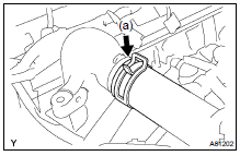
(b) Lock the hose clamp, as shown in the illustration.
(c) Disconnect the heater inlet water hose.

(d) Remove the nut and disconnect the ground cable.
(e) Disconnect the 6 fuel injector connectors.

(f) Loosen and remove the intake manifold's 9 bolts and 2 nuts little by little in the numerical order shown in the illustration.
(g) Remove the intake manifold.
NOTICE: Fully removing each bolt and nut one by one may damage the intake manifold, bolts and nuts.
8. REMOVE ENGINE MOVING CONTROL ROD (See page 14-149 )
9. REMOVE WATER OUTLET

(a) Disconnect the radiator hose inlet.

(b) Disconnect the ECT sensor connector.
(c) Remove the clamp.
(d) Remove the 2 bolts, 2 nuts and 2 washers.
(e) Lock the hose clamp as shown in the illustration. Then remove the water outlet together with the water by-pass hose No. 1.
(f) Remove the 2 gaskets from the 2 cylinder heads.
10. REMOVE KNOCK SENSOR

(a) Disconnect the 2 sensor connectors.
(b) Remove the 2 nuts and 2 sensors.
11. INSTALL KNOCK SENSOR

(a) Install the 2 sensors with the 2 nuts, as shown in the illustration.
Torque: 20 NVm (199 kgfVcm, 14 ftVlbf) (b) Connect the 2 sensor connectors.
12. INSTALL WATER OUTLET
(a) Install 2 new gaskets to the 2 cylinder heads.
(b) Install the water outlet together with the water by-pass hose No. 1 and unlock the hose clamp.
(c) Tighten the 2 bolts, 2 nuts and 2 washers.
Torque: 15 NVm (153 kgfVcm, 11 ftVlbf) (d) Install the clamp.
(e) Connect the ECT sensor connector.
(f) Connect the radiator hose inlet.
13. INSTALL ENGINE MOVING CONTROL ROD (See page 14-149 )
14. INSTALL INTAKE MANIFOLD

(a) Tighten the intake manifolds's 9 bolts and 2 nuts little by little in the numerical order shown in the illustration.
Torque: 15 NVm (153 kgfVcm, 11 ftVlbf)
NOTICE: In this case, fully tightening one of these bolts or nuts without partially tightening the other bolts or nuts in the group may damage the intake manifold, bolts and nuts.
(b) Retighten the water outlet mounting bolts and nuts.
Torque: 15 NVm (153 kgfVcm, 11 ftVlbf) (c) Install the ground cable with the nut.
Torque: 8.4 NVm (86 kgfVcm, 74 in.Vlbf) (d) Connect the heater inlet water hose.

(e) Connect the fuel pipe No. 1.
- Push the quick connector into the pipe until it makes "click" sound.
NOTICE:
- Check if there is any damage or contamination on the connected part.
- After connecting, confirm that the connector and pipe are securely connected by trying to pull them apart.
- Install the fuel pipe clamp.
15. INSTALL INTAKE AIR SURGE TANK (See page 14-149 )
16. INSTALL EMISSION CONTROL VALVE SET (See page 14-149 )
17. INSTALL AIR CLEANER CAP SUB-ASSY (See page 14-149 )
18. CHECK CONNECTION OF VACUUM HOSE (See page 14-149 )
19. ADD ENGINE COOLANT (See page 16-26 )
20. CHECK FOR ENGINE COOLANT LEAKS (See page 16-20 )
21. CHECK FOR FUEL LEAKS
22. INSTALL V-BANK COVER SUB-ASSY (See page 14-149 )
 Throttle body ASSY (3MZ-FE)
COMPONENTS
REPLACEMENT
1. DRAIN ENGINE COOLANT (See page 16-26 )
2. REMOVE FRONT SUSPENSION BRACE SUB-ASSY UPPER CENTER
(a) Remove the 2 nuts and upper brace.
3. REMOVE V-BANK COVER SUB-A ...
 ECM (3MZ-FE)
REPLACEMENT
1. DISCONNECT BATTERY NEGATIVE TERMINAL
2. REMOVE FRONT DOOR SCUFF PLATE RH (See page 71-10 )
3. REMOVE COWL SIDE TRIM SUB-ASSY RH (See page 71-10 )
4. REMOVE GLOVE COMPARTMENT DOOR AS ...
More about Toyota Highlander:
Armrest
Type a
Fold down the armrest for use.
Type b
Lower the armrest from the
highest position to the lowest
position.
Raise the armrest to the
desired angle.
To unlock the armrest, lift the armrest
to raise it to the highest position.
Notice
To prevent d ...
