Toyota Highlander Service Manual: Inspection
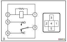
1. INSPECT DEFOGGER RELAY

(a) Inspect the defogger relay (Marking: DEF) continuity

If the continuity is not as specified, replace the relay.
2. INSPECT AIR CONDITONER CONTROL ASSY (SEE PAGE 55-7 )
3. INSPECT BACK WINDOW (DEFOGGER WIRE)

NOTICE:
- When cleaning the glass, wipe the glass along the wire using a soft and dry cloth. Take care not to damage the wires.
- Do not use detergents or glass cleaners including abrasive ingredients.
- When measuring voltage, wrap a piece of tin foil around the tip of the negative tester probe and press the foil against the wire with your finger, as shown in the illustration.

(a) Turn the ignition switch ON.
(b) Turn the defogger switch ON.
(c) Check the voltage at the center of each defogger wire, as shown in the illustration.
Standard:


HINT: If there is approx 10 V, the wire may be broken between the center of the wire and the end on the battery side. If there is no voltage, the wire may be broken between the center of the wire and the end on the ground side.
(d) Place the voltmeter positive (+) lead against the defogger wire on the battery side.
(e) Place the voltmeter negative (-) lead with the foil strip against the wire on the ground side.
(f) Slide the positive (+) lead from the battery side to the ground side.
(g) The point where the voltmeter deflects from approx 10 V to 0 V is the place where the defogger wire is broken.
HINT: If the defogger wire is not broken, the voltmeter indicates 0 V at the positive (+) end of the defogger wire but gradually increases to approx 12 V as the meter probe moves to the other end.

(h) If necessary, repair the defogger wire.
- Clean the broken wire tips with grease, wax and silicone remover.
- Place the masking tape along both sides of the wire.
- Thoroughly mix the repair agent (Dupont paste No.
4817).

- Using a fine tip brush, apply a small amount of the agent to the wire.
- After a few minutes, remove the masking tape.
NOTICE: Do not repair the defogger wire again for at least 24 hours.
 Location
PROBLEM SYMPTOMS TABLE
Symptom
Suspected Area
Rear window defogger does not operate
(Indicator lamp On)
Communication Function
RR DEF 30 A Fuse
...
More about Toyota Highlander:
Registering a bluetoothÂź
device
BluetoothÂź compatible phones (hfp) and portable audio players
(avp) can be registered simultaneously. You can register up to 5
bluetoothÂź devices.
How to register a bluetoothÂź device
Display the "bluetooth* setup" screen.
*: Bluetooth is a registered trademark of bluetooth sig ...

