Toyota Highlander Service Manual: Front axle hub sub-ASSY LH
REPLACEMENT
HINT: COMPONENTS: SEE PAGE 30-4 Replace the RH side by the same procedures with LH side.
1. REMOVE FRONT WHEEL
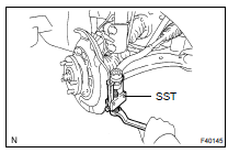
2. REMOVE FRONT AXLE HUB LH NUT
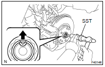
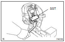
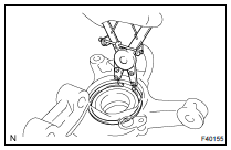
(a) Using SST and a hammer, unstake the staked part of the lock nut.
SST 09930-00010
(b) While applying the brakes, remove the lock nut.
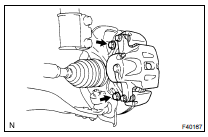
3. SEPARATE SPEED SENSOR FRONT LH
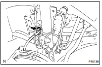
(a) Remove the bolt, separate the sensor wire and flexible hose from the shock absorber
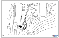
(b) Remove the bolt and separate the speed sensor from the steering knuckle.
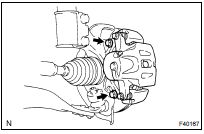
4. SEPARATE FRONT DISC BRAKE CALIPER ASSY LH
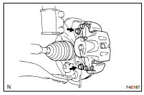
(a) Remove the 2 bolts, separate the brake caliper.
5. REMOVE FRONT DISC
6. SEPARATE TIE ROD END SUB-ASSY LH
(a) Remove the cotter pin and nut.
(b) Using SST, separate the tie rod end from the steering knuckle.
SST 09628-6201 1
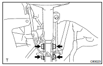
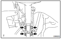
7. SEPARATE FRONT SUSPENSION ARM SUB-ASSY LOWER NO.1 LH
(a) Remove the bolt and 2 nuts, and separate the lower suspension arm from the lower ball joint.
8. REMOVE FRONT AXLE ASSY LH
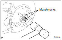
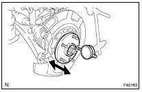
(a) Put matchmarks on the drive shaft and the axle hub.
(b) Using a plastic hammer, separate the drive shaft from the axle hub.
NOTICE: Be careful not to damage the boot and speed sensor rotor.
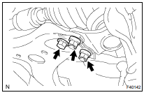
(c) Remove the 2 bolts, nuts and steering knuckle with the axle hub.
9. REMOVE LOWER BALL JOINT ASSY FRONT LH
(a) Remove the cotter pin and nut.
(b) Using SST, remove the ball joint.
SST 09628-6201 1
10. REMOVE FRONT WHEEL BEARING DUST DEFLECTOR NO.1 LH
(a) Using a screwdriver, remove the dust deflector.
11. REMOVE FRONT AXLE HUB LH HOLE SNAP RING

(a) Using a snap ring plier, remove the snap ring.
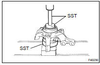
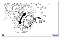
12. REMOVE FRONT AXLE HUB SUB-ASSY LH
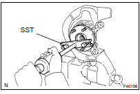
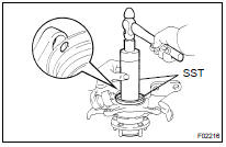
(a) Using SST, remove the axle hub.
(b) Using SST and a press, remove the inner race (outside) from the axle hub.
SST 09520- 00031, 09950- 00020, 09950- 60010 (09951-00430), 09950-70010 (09951-07100)
13. REMOVE DISC BRAKE DUST COVER FRONT LH
(a) Using a torx) wrench (T30), remove the 4 bolts and dust cover.
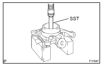
14. REMOVE FRONT AXLE HUB LH BEARING
(a) Place the inner race (outside) on the bearing.
(b) Using SST and a press, press the bearing until it contacts with the SST.
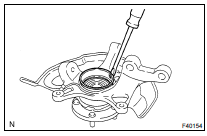
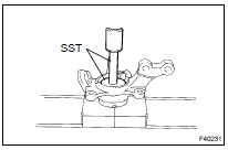
c) Using a spanner to make the steering knuckle horizontal, fix it to the V block as shown in the illustration.
NOTICE: Be sure the steering knuckle is horizontally positioned.
(d) Using SST and a press, remove the bearing.
SST 09527- 17011, 09950- 60020 (09951- 00750), 09950-70010 (09951-07100)
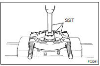
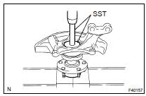
15. INSTALL FRONT AXLE HUB LH BEARING
(a) Using SST and a press, install a new bearing to the steering knuckle.
SST 09608- 32010, 09950- 60020 (09951- 00810), 09950-70010 (09951-07100)
16. INSTALL DISC BRAKE DUST COVER FRONT LH
(a) Place the dust cover and using a torx) wrench (T30), torque the 4 bolts.
17. INSTALL FRONT AXLE HUB SUB-ASSY LH
(a) Using SST and a press, install the axle hub.
SST 09608- 32010, 09950- 60020 (09951- 00810), 09950-70010 (09951-07100)
18. INSTALL FRONT AXLE HUB LH HOLE SNAP RING
(a) Using snap ring pliers, install a new snap ring.
19. INSTALL FRONT WHEEL BEARING DUST DEFLECTOR NO.1 LH
(a) Using SST and a hammer, install a new dust deflector.
SST 09316- 60011 (09316- 00011, 09316- 00031), 09608-32010
HINT: Align the holes for the ABS speed sensor in the dust deflector with steering knuckle.
20. INSTALL LOWER BALL JOINT ASSY FRONT LH
(a) Install the lower ball joint and tighten the nut.
Torque: 123 NVm (1,250 kgfVcm, 90 ftVlbf)
(b) Install a new cotter pin.
If the holes for the cotter pin are not aligned, tighten the nut further up to 60 .
21. INSTALL FRONT AXLE ASSY LH

(a) Align the matchmarks and install the drive shaft assy LH to the front axle assy LH.
(b) Install the 2 bolts, nuts and axle assembly to the shock absorber.
Torque: 230 NVm (2,345 kgfVcm, 170 ftVlbf)
HINT: Insert the bolt from the front side of the vehicle and tighten the nut.
(c) Push the front axle assy toward the outside of the vehicle, fit the spline part of the drive shaft assy to that of the front axle assy and insert the drive shaft assy into the front axle assy.
NOTICE:
- Do not push out the front axle assy excessively.
- Be careful not to damage the drive shaft outboard joint boot.
- Be careful not to damage the speed sensor rotor.
22. INSTALL FRONT SUSPENSION ARM SUB-ASSY LOWER NO.1 LH
(a) Connect the lower arm and ball joint with the 2 nuts and bolt.
23. INSTALL TIE ROD END SUB-ASSY LH
(a) Connect the tie rod end to the steering knuckle.
(b) Install the nut and a new cotter pin.
Torque: 49 NVm (500 kgfVcm, 36 ftVlbf)
24. INSTALL FRONT DISC
25. INSTALL FRONT DISC BRAKE CALIPER ASSY LH
(a) Install the brake caliper assembly with the 2 bolts to the steering knuckle.
Torque: 107 NVm (1,090 kgfVcm, 79 ftVlbf)
26. INSTALL FRONT AXLE HUB LH NUT
27. SEPARATE FRONT DISC BRAKE CALIPER ASSY LH
28. REMOVE FRONT DISC
29. INSPECT BEARING BACKLASH
(a) Using a dial indicator, check the backlash near the center of the axle hub.
Maximum: 0 mm (0 in.)
If the backlash exceeds the maximum, replace the bearing.
30. INSPECT AXLE HUB DEVIATION
(a) Using a dial indicator, check the deviation at the surface of the axle hub outside the hub bolt.
Maximum: 0.07 mm (0.0027 in.)
If the backlash exceeds the maximum, replace the axle hub.
31. INSTALL FRONT DISC
32. INSTALL FRONT DISC BRAKE CALIPER ASSY LH
(a) Install the brake caliper assy with the 2 bolts to the steering knuckle.
Torque: 107 NVm (1,090 kgfVcm, 79 ftVlbf)
33. INSTALL SPEED SENSOR FRONT LH
34. INSTALL FRONT WHEEL Torque: 103 NVm (1,050 kgfVcm, 76 ftVlbf)
35. INSPECT AND ADJUST FRONT WHEEL ALIGNMENT (SEE PAGE 26-7 )
36. CHECK ABS SPEED SENSOR SIGNAL (SEE PAGE 05-765 )
 Front drive shaft
OVERHAUL
HINT:
COMPONENTS: SEE PAGE 30-4
Overhaul the RH side following the same procedures as for the LH side.
1. DRAIN AUTOMATIC TRANSAXLE FLUID (SEE PAGE 40-2 )
2. DRAIN TRANSFER OIL (4WD DRIV ...
 Front axle LH hub bolt
REPLACEMENT
HINT:
COMPONENTS:SEE PAGE 30-4
Replace the RH side by the same procedures with LH side.
1. REMOVE FRONT WHEEL
2. SEPARATE FRONT DISC BRAKE CALIPER ASSY
LH(SEE PAGE 30-38 )
3. REMOVE ...
More about Toyota Highlander:
Outside vehicle
GENERAL MAINTENANCE
HINT:
These are maintenance and inspection items which are considered to be the
owner's responsibility.
They can be done by the owner or they can have them done at a service shop.
These items include those which should be checked on a daily basis, those which,
in most ...
