Toyota Highlander Service Manual: Engine rear oil seal (2AZ-FE)
REPLACEMENT
1. REMOVE AUTOMATIC TRANSAXLE ASSY (See page 40-12 )
HINT: Remove and install the transaxle after removing the engine assy w/ transaxle.
2. REMOVE DRIVE PLATE & RING GEAR SUB-ASSY
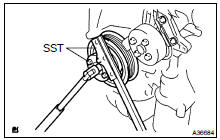
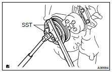
(a) Using SST, fix the crankshaft.
SST 09213-54015 (91651-60855), 09330-00021
(b) Remove the 8 bolts, rear spacer, drive plate and front spacer.
3. REMOVE ENGINE REAR OIL SEAL
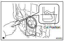
(a) Using a knife, cut through the oil seal lip.
(b) Using a screwdriver with its tip taped, pry out the oil seal.
NOTICE: After the removal, check the crankshaft for damage. If it is damaged, smooth the surface with 400-grit sandpaper.
4. INSTALL ENGINE REAR OIL SEAL
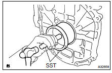
(a) Apply MP grease to a new oil seal lip.
NOTICE: Keep the lip free from foreign matter.
(b) Using SST and a hammer, tap in the oil seal until its surface is flush with the rear oil seal retainer edge.
SST 09223-15030, 09950-70010 (09951-07100)
NOTICE: Wipe off extra grease from the crankshaft.
5. INSTALL DRIVE PLATE & RING GEAR SUB-ASSY
(a) Using SST, fix the crankshaft.
SST 09213-54015 (91651-60855), 09330-00021
(b) Clean the bolt and the bolt hole.
(c) Apply adhesive to 2 or 3 threads of the bolt end.
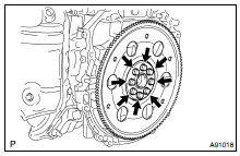
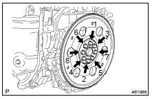
Adhesive: Part No. 08833-00070, THREE BOND or equivalent (d) Install the front spacer, drive plate and rear spacer with the 8 bolts. Uniformly tighten the bolts in the sequence shown in the illustration.
Torque: 98 NVm (1,000 kgfVcm, 72 ftVlbf)
6. INSTALL AUTOMATIC TRANSAXLE ASSY (See page 40-12 )
 Timing gear case or timing chain case oil
seal (2AZ-FE)
Timing gear case or timing chain case oil
seal (2AZ-FE)
REPLACEMENT
1. REMOVE FRONT WHEEL RH
2. REMOVE FRONT FENDER SPLASH SHIELD FRONT RH
3. REMOVE FRONT FENDER APRON SEAL RH
4. REMOVE ENGINE COVER SUB-ASSY NO.1
5. REMOVE ENGINE MOUNTING STAY NO.2 RH ...
 Cylinder head ASSY (2AZ-FE)
COMPONENTS
OVERHAUL
1. REMOVE VALVE LIFTER
HINT:
Arrange the valve lifters in the correct order.
2. REMOVE INTAKE VALVE
(a) Using SST and wooden blocks, compress and remove
the 8 valve ...
More about Toyota Highlander:
Air outlets
Location of air outlets
The air outlets and air volume
change according to the
selected airflow mode.
Adjusting the position of and opening and closing the air outlets
Direct air flow to the left or right,
forward or backward.
Closes the vent
slide the knob to the rear-most
pos ...
