Toyota Highlander Service Manual: Valve clearance (2AZ-FE)
ADJUSTMENT
1. REMOVE FRONT WHEEL RH
2. REMOVE FRONT FENDER SPLASH SHIELD FRONT RH
3. REMOVE FRONT FENDER APRON SEAL RH
4. REMOVE ENGINE COVER SUB-ASSY NO.1
5. REMOVE IGNITION COIL ASSY
6. REMOVE SPARK PLUG
7. DISCONNECT VENTILATION HOSE
8. DISCONNECT VENTILATION HOSE NO.2
9. REMOVE CYLINDER HEAD COVER SUB-ASSY
- Remove the bolt and disconnect the engine wire harness clamp.
- Remove the 8 bolts, 2 nuts, cylinder head cover and gasket.
10. SET NO. 1 CYLINDER TO TDC/COMPRESSION
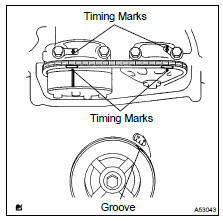
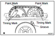
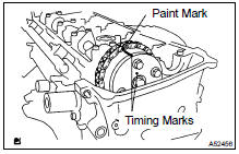
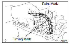
- Turn the crankshaft pulley, and align its groove with timing mark 0 of the timing chain cover.
- ) Check that the timing marks of the camshaft timing gear and sprocket are aligned with the timing marks of the bearing cap No. 1 and No. 2 as shown in the illustration.
11. INSPECT VALVE CLEARANCE
HINT: Inspect and adjust the valve clearance when the engine is cold.
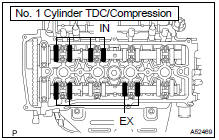
(a) Check only the valve indicated on the left.
- Using a feeler gauge, measure the clearance between the valve lifter and camshaft.
- Record valve clearance measurements that are out of the specified range. These measurements will be used later to determine the size of the adjustment shim to be installed.
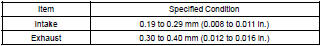
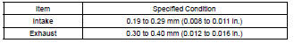
Valve clearance (Cold):
(b) Turn the crankshaft clockwise 1 revolution (360 ) and set the No.4 cylinder to TDC/compression.
(c) Check only the valve indicated on the left.
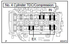
- Using a feeler gauge, measure the clearance between the valve lifter and camshaft.
- Record valve clearance measurements that are out of the specified range. These measurements will be used later to determine the size of the adjustment shim to be installed.
Valve clearance (Cold):
12. ADJUST VALVE CLEARANCE
NOTICE: Be sure not to turn the crankshaft without the chain tensioner.
(a) Turn the crankshaft clockwise 1 revolution (360 ) and set the No. 1 cylinder to the TDC/compression.
(b) Place paint marks on the timing chain and camshaft timing gear sprocket.
(c) Remove the 2 bolts and chain tensioner.
(d) Remove the No. 2 camshaft.
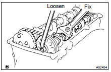
- Fix the camshaft with a wrench and then loosen the sprocket bolt.
NOTICE: Be careful not to damage the valve lifter.
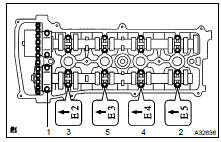
- Uniformly loosen and remove the No. 2 camshaft's 10 bearing cap bolts in the sequence shown in the illustration. Then remove the 5 bearing caps.
- Raise the No. 2 camshaft and remove it. Then remove the sprocket bolt.
- Remove the camshaft timing sprocket and the timing chain from the No. 2 camshaft.
- Remove the camshaft timing sprocket from the timing chain.
(e) Remove the camshaft.
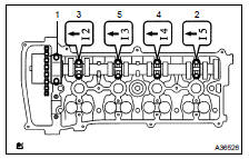
- Uniformly loosen and remove the camshaft's 10
bearing cap bolts in the sequence shown in the illustration.
Then remove the 5 bearing caps.
- Remove the camshaft.
(f) Tie the timing chain with a string.
NOTICE: Be careful not to drop anything inside the timing chain cover.
(g) Remove the valve lifters.
(h) Adjust the valve clearance.
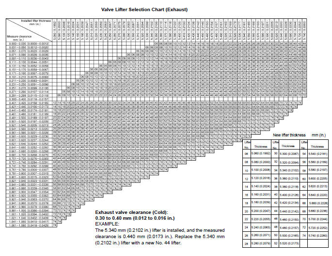
- Using a micrometer, measure the thickness of the removed lifter.
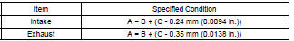
- Calculate the thickness of a new lifter so that the valve clearance comes within the specified value.
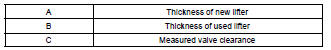
Valve clearance:
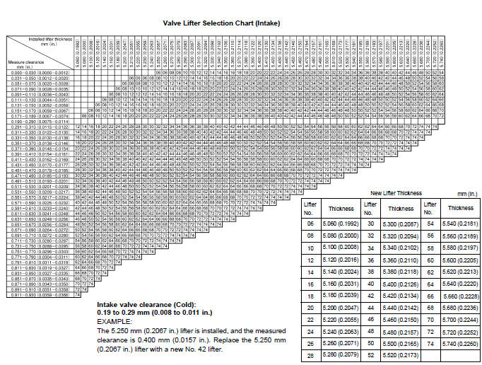
EXAMPLE: (Intake)
Measured valve clearance = 0.44 mm (0.0173 in.)
0.44 mm (0.0173 in.) - 0.24 mm (0.0094 in.) = 0.20 mm (0.0079 in.)
(Measured - Specification = Excess clearance)
Used shim measurement = 5.30 mm (0.2087 in.)
0.20 mm (0.0079 in.) + 5.30 mm (0.2087 in.) = 5.50 mm (0.2165 in.)
(Excess clearance + Used shim = Ideal new shim)
Closest new shim = 5.50 mm (0.2165 in.) = Shim No. "50"
- Select a new lifter with a thickness as close as possible to the calculated values.
HINT:
- Lifters are available in 35 sizes in increments of 0.020 mm (0.0008 in.), from 5.060 mm (0.1992 in.) to 5.740 mm (0.2260 in.).
- Refer to valve lifter selection chart on the following 2 pages.
(i) Install the camshaft.
- Install the timing chain on the camshaft timing gear, with the paint mark aligned with the timing marks on the camshaft timing gear.
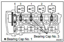
- Examine the front marks and numbers of the 5 bearing caps and install them. Then install the 10 bearing cap bolts. Uniformly tighten the bolts in the sequence shown in the illustration.
Torque: 30 NVm (301 kgfVcm, 22 ftVlbf) for bearing cap No. 1 9.0 NVm (92 kgfVcm, 80 in.Vlbf) for bearing cap No. 3
(j) Install the No. 2 camshaft.
- Put the No. 2 camshaft on the cylinder head with the paint mark of the chain aligned with the timing mark on the camshaft timing sprocket.
- Raise the No. 2 camshaft and temporarily tighten the sprocket bolt.
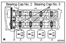
- Examine the front marks and numbers of the 5 bearing caps and install them. Then install the 10 bearing cap bolts. Uniformly tighten the bolts in the sequence shown in the illustration.
Torque: 30 NVm (301 kgfVcm, 22 ftVlbf) for bearing cap No. 2 9.0 NVm (92 kgfVcm, 80 in.Vlbf) for bearing cap No. 3
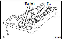
- Fix the camshaft with a wrench, then tighten the sprocket bolt.
Torque: 54 NVm (551 kgfVcm, 40 ftVlbf)
NOTICE: Be careful not to damage the valve lifter.
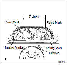
(k) Check that the timing chain paint marks are aligned with the camshaft timing sprocket timing mark and the camshaft timing gear timing mark. Also check the alignment of the pulley groove and chain cover timing mark.
(l) Install the chain tensioner.
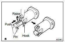
- Release the ratchet pawl, fully push in the plunger and apply the hook to the pin so that the plunger cannot spring out.
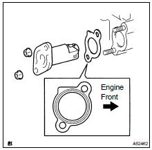
- Install a new gasket and the chain tensioner with the 2 nuts.
Torque: 9.0 NVm (92 kgfVcm, 80 in.Vlbf)
NOTICE: When installing the tensioner, set the hook again if the hook releases the plunger.
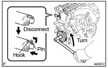
- Turn the crankshaft counterclockwise, and disconnect the plunger knock pin from the hook.
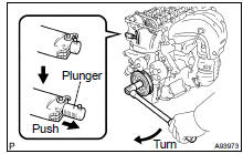
- Turn the crankshaft clockwise, and check that the slipper is pushed by the plunger.
13. INSTALL CYLINDER HEAD COVER SUB-ASSY
(a) Remove any old packing (FIPG) material
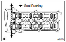
(b) Apply seal packing to 2 locations as shown in the illustration.
Seal packing: Part No. 08826-00080 or equivalent
NOTICE:
- Remove any oil from the contact surface.
- Install the cylinder head cover within 5 minutes after applying seal packing.
- Do not start the engine for at least 2 hours after installing the cylinder head cover.
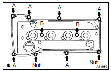
(c) Install the cylinder head cover with the 8 bolts and 2 nuts.
Torque: 11 NVm (112 kgfVcm, 8 ftVlbf) for nut 11 NVm (112 kgfVcm, 8 ftVlbf) for bolt A 14 NVm (143 kgfVcm, 10 ftVlbf) for bolt B
14. INSTALL SPARK PLUG Torque: 19 NVm (194 kgfVcm, 14 ftVlbf)
15. INSTALL IGNITION COIL ASSY Torque: 9.0 NVm (92 kgfVcm, 80 in.Vlbf)
16. INSTALL FRONT WHEEL RH
17. CHECK FOR ENGINE COOLANT LEAKS (See page 16-6 )
 Fan and generator v belt (2AZ-FE)
REPLACEMENT
1. REMOVE FRONT WHEEL RH
2. REMOVE FRONT FENDER SPLASH SHIELD FRONT RH
3. REMOVE FRONT FENDER APRON SEAL RH
4. REMOVE ENGINE MOUNTING STAY NO.2 RH
5. REMOVE ENGINE COVER SUB-ASSY NO.1 ...

More about Toyota Highlander:
On-vehicle inspection
1. INSPECT AIR-FUEL RATIO COMPENSATION SYSTEM
(a) Measure the voltage between the terminals of the ECM
connectors.
Standard:
NOTICE:
Connect test leads to the connector's backside. The connectors
should not be disconnected from the ECM.
HINT:
Voltage between the terminals of the EC ...
