Toyota Highlander Service Manual: Rear suspension arm ASSY NO.1 LH (FF)
REPLACEMENT
HINT: COMPONENTS: See page 27-2 .
1. REMOVE REAR WHEEL
2. REMOVE STABILIZER BAR REAR (SEE PAGE 27-27 )
3. REMOVE REAR SUSPENSION ARM ASSY NO.1 LH
(a) Support the rear axle carrier with a jack.
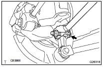
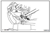
(b) Remove the bolt and disconnect the rear suspension arm assy No.1 (inner side).
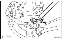
(c) Remove the bolt, nut and the rear suspension arm assy No.1 (outer side) from the rear axle carrier.
NOTICE: When removing the bolt, keep the nut from rotating.
4. TEMPORARILY TIGHTEN REAR SUSPENSION ARM ASSY NO.1 LH
(a) Install the rear suspension arm assy No.1 (inner side) with the bolt, and temporarily tighten the bolt.
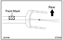
HINT: Ensure that the paint mark on the rear suspension arm assy No.1 faces the rear side of the vehicle.
(b) Connect the rear suspension arm assy No.1 (outer side) to the rear axle carrier with the bolt and nut and temporarily tighten the bolt and nut.
NOTICE: When installing the bolt, fix the nut and temporarily tighten the bolt.
5. STABILIZE SUSPENSION (SEE PAGE 27-13 )
6. FULLY TIGHTEN REAR SUSPENSION ARM ASSY NO.1 LH
(a) Fully tighten the bolt.
Torque: 120 NVm (1,220 kgfVcm, 89 ftVlbf)
(b) Fully tighten the bolt.
Torque: 112 NVm (1,140 kgfVcm, 83 ftVlbf)
7. INSTALL STABILIZER BAR REAR (SEE PAGE 27-27 )
8. INSTALL REAR WHEEL Torque: 103 NVm (1,050 kgfVcm, 76 ftVlbf)
9. INSPECT REAR WHEEL ALIGNMENT (SEE PAGE 27-5 )
 Strut rod ASSY rear
HINT:
COMPONENTS: See page 27-2 .
1. REMOVE REAR WHEEL
2. REMOVE STRUT ROD ASSY REAR
(a) Support the rear axle carrier with a jack.
(b) Remove the bolt and nut, and separate the parking b ...
 Rear suspension arm ASSY NO.1 LH (4WD)
REPLACEMENT
HINT:
COMPONENTS: See page 27-2 .
1. REMOVE REAR WHEEL
2. REMOVE EXHAUST PIPE ASSY
(a) 2AZ-FE (see page 15-2 )
(b) 3MZ-FE (see page 15-5 )
3. REMOVE PROPELLER W/CENTER BEARING SHAFT ...
More about Toyota Highlander:
Update contacts from phone
Operation methods differ between pbap compatible and pbap
incompatible but opp compatible bluetoothr phones.
If your cellular phone is neither pbap nor opp compatible, the contacts
cannot be transferred.
For pbap compatible bluetoothr phones
Select "update contacts from phone&qu ...
