Toyota Highlander Service Manual: Propeller W/Center bearing shaft Propeller w/center bearing shaft
OVERHAUL
HINT: COMPONENTS:SEE PAGE 30-4
1. REMOVE EXHAUST PIPE ASSY
2. REMOVE PROPELLER W/CENTER BEARING SHAFT ASSY
(a) Depress the brake pedal and hold it.
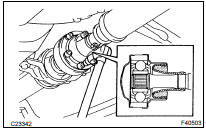
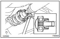
(b) Using a hexagon wrench (6 mm), loosen the cross groove joint set bolts 1/2 turn.
HINT: Put a piece of shop rag or equivalent into the inside of the universal joint cover so that the boot does not touch the inside of the universal joint cover.
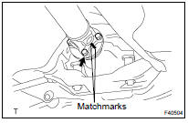
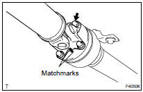
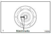
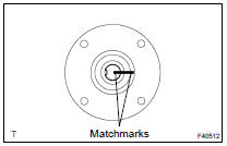
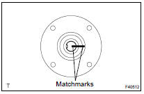
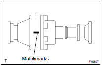
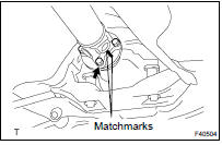
(c) Place matchmarks on both the flanges.
(d) Remove the 4 nuts, bolts and washers.
(e) Remove the 4 bolts, 2 adjusting shims and propeller shaft w/ center bearing shaft assy.
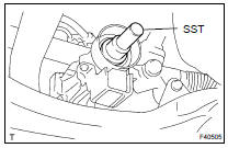
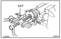
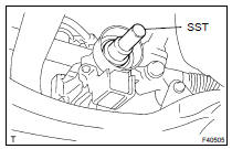
(f) Insert SST in the transfer to prevent oil leakage.
SST 09325-20010
3. REMOVE PROPELLER SHAFT ASSY
(a) Place matchmarks on both the flanges.
(b) Remove the 4 nuts, bolts and washers.
4. REMOVE INTERMEDIATE SHAFT
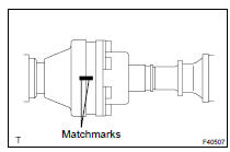
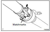
(a) Place matchmarks on the joint and flange.
NOTICE: Do not make matchmarks with a punch.
(b) Using a hexagon wrench (6 mm), remove the 6 bolts and 2 washers and separate the intermediate shaft from the rear propeller shaft.
5. INSPECT SPIDER BEARING
(a) Check the spider bearing axial play by turning the flange while holding the shaft tightly.
HINT: If necessary, replace the shaft.
6. INSPECT INTERMEDIATE SHAFT
(a) Using a dial indicator, inspect the runout of the shaft.
Maximum runout: 0.8 mm (0.031 in.)
HINT: If the shaft runout exceeds the maximum, replace the shaft.
(b) Using a dial indicator, inspect the front side of the intermediate shaft flange runout.
Maximum runout: 0.1 mm (0.004 in.)
HINT: If the shaft runout exceeds the maximum, replace the shaft.
(c) Using a dial indicator, inspect the rear side of the intermediate shaft flange runout in the horizontal direction.
Maximum runout: 0.1 mm (0.004 in.)
HINT: If the intermediate shaft flange runout exceeds the maximum, replace the intermediate shaft.
(d) Using a dial indicator, inspect the rear side of the intermediate shaft flange runout in the vertical direction.
Maximum runout: 0.1 mm (0.004 in.)
HINT: If the intermediate shaft flange runout exceeds the maximum, replace the intermediate shaft.
7. INSPECT PROPELLER SHAFT ASSY
(a) Using a dial indicator, inspect the runout of the propeller shaft.
Maximum runout: 0.8 mm (0.031 in.)
HINT: If the shaft runout exceeds the maximum, replace the propeller shaft.
8. REMOVE CENTER SUPPORT BEARING ASSY NO.2
(a) Using a chisel and a hammer, loosen the staked part of the nut.
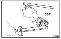
(b) Using SST to hold the front flange, remove the nut and plate washer.
SST 09330-00021
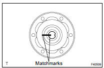
(c) Place matchmarks on the rear flange and shaft.
(d) Using SST, remove the rear flange.
SST 09950- 40011 (09951- 04020, 09952- 04010, 09953- 04030, 09954- 04010, 09955- 04061, 09957-04010, 09958-04011)
(e) Remove the center support bearing assy No.2 and plate washer.
9. REMOVE CENTER SUPPORT BEARING ASSY NO.1
(a) Using a chisel and a hammer, loosen the staked part of the nut.
(b) Using SST to hold the front flange, remove the nut and plate washer.
SST 09330-00021
(c) Place matchmarks on the front flange and shaft.
(d) Using SST, remove the front flange.
SST 09950- 40011 (09951- 04020, 09952- 04010, 09953- 04030, 09954- 04010, 09955- 04061, 09957-04010, 09958-04011)
(e) Remove the center support bearing assy No.1 and plate washer.
10. INSPECT CENTER SUPPORT BEARING ASSY NO.2
(a) Turn the bearing by hand with applying force in the rotation direction. Check the bearing turns smoothly.
(b) Check that the seals are not cracked or damaged.
HINT: If the bearing is damaged, worn, or does not turn freely, replace it.
11. INSPECT CENTER SUPPORT BEARING ASSY NO.1
(a) Inspect the center support bearing assy No.1 by the same procedures with center support bearing assy No.2.
12. INSPECT PROPELLER SHAFT
(a) Using a dial indicator, inspect the runout of the rear propeller shaft.
Maximum runout: 0.8 mm (0.031 in.)
HINT: If the shaft runout exceeds the maximum, replace the rear propeller shaft.
13. INSTALL CENTER SUPPORT BEARING ASSY NO.1
(a) Set the center support bearing assy No.1 on the intermediate shaft, as shown in the illustration.
(b) Install the plate washer to the intermediate shaft.
(c) Align the matchmarks on the front flange and shaft and place the flange on the shaft.
(d) Using SST to hold the front flange, press the center support bearing assy No.1 into position by tightening down a new nut and plate washer.
SST 09330-00021
Torque: 182 N*m (1,850 kgf*cm, 134 ft*lbf)
(e) Loosen the nut.
(f) Torque the nut again.
Torque: 69 N*m (700 kgf*cm, 51 ft*lbf)
(g) Using a chisel and a hammer, stake the nut.
14. INSTALL CENTER SUPPORT BEARING ASSY NO.2
(a) Set the center support bearing assy No.2 on the shaft as shown in the illustration.
(b) Install the plate washer to the shaft.
(c) Align the matchmarks on the rear flange and shaft and place the flange on the shaft.
(d) Using SST to hold the front flange, press the center support bearing assy No.2 into position by tightening down a new nut and plate washer.
SST 09330-00021
Torque: 182 N*m (1,850 kgf*cm, 134 ft*lbf)
(e) Loosen the nut.
(f) Torque the nut again.
Torque: 69 N*m (700 kgf*cm, 51 ft*lbf)
(g) Using a chisel and a hammer, stake the nut.
15. INSTALL INTERMEDIATE SHAFT
(a) Align the matchmarks on the intermediate shaft and rear propeller shaft, then install the 2 washers and 6 bolts.
(b) Using a hexagon wrench (6 mm), tighten the 6 bolts temporarily.
16. INSTALL PROPELLER SHAFT ASSY
(a) Align the matchmarks on the propeller shaft flange and differential companion flange, and connect the shaft with the 4 bolts, washers and nuts.
Torque: 74 N*m (750 kgf*cm, 54 ft*lbf)
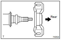
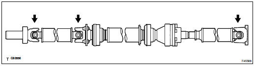
(b) Check that the each joint of the propeller shaft is facing to the direction, as shown in the illustration.
17. INSTALL PROPELLER W/CENTER BEARING SHAFT ASSY
(a) Align the matchmarks on the propeller shaft flange and differential companion flange, and connect the shaft with the 4 bolts, washers and nuts.
(b) Remove SST from the transaxle.
(c) Insert the yoke into the transaxle.
(d) Install the 2 adjusting shims and propeller shaft w/ center bearing, and temporarily tighten the 4 bolts.
(e) Tighten the 4 nuts.
Torque: 74 N*m (750 kgf*cm, 54 ft*lbf)
18. FULLY TIGHTEN PROPELLER W/CENTER BEARING SHAFT ASSY
(a) Remove the shop rag to the joint.
(b) Using a hexagon wrench (6 mm), tighten the 6 bolts.
Torque: 29 N*m (296 kgf*cm, 21 ft*lbf)
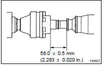
(c) With the vehicle unloaded, adjust the dimension between the rear side of the cover and shaft, as shown in the illustration.
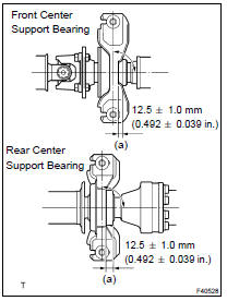
(d) Under the same condition as (a), adjust the front and rear dimensions between edge surface of the center support bearing and the edge surface of the cushion to 12.5 1.0 mm (0.492 0.039 in.) respectively as shown, then torque the bolts.
Torque: 37 N*m (375 kgf*cm, 27 ft*lbf)
(e) Check that the center line of the bracket is at the right angle in the shaft axial direction.
(f) If any vibration or noise occurs, perform joint angle check as follows and replace the adjusting shim with proper one.
- Turn the propeller shaft several times by hand to stabilize the center support bearings.
- Using a jack, raise and lower the differential to stabilize the differential mounting cushion.
- Remove the transfer dynamic damper.
- Using SST, measure the installation angle of the
transfer (A) and front propeller shaft (B).
SST 09370-50010
No.1 joint angle: A - B = -1.6 to -3.6 - Using SST, measure the installation angle of the
rear propeller shaft (C) and rear differential (D).
SST 09370-50010
No.2 joint angle: C - D = 2.1 to 4.1
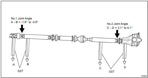
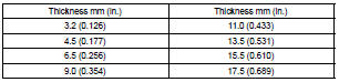
HINT: If the measured angle is not within the specification, adjust it with the center support bearing adjusting shim.
Center support bearing adjusting shim thickness:
(g) Install the transfer dynamic damper.
Torque: 26 N*m (260 kgf*cm, 19 ft*lbf)
19. INSTALL EXHAUST PIPE ASSY
20. CHECK FOR EXHAUST GAS LEAKS
21. INSPECT AND ADJUST TRANSFER OIL
 Drive shaft / propeller shaft / axle
COMPONENTS
...
 Front drive shaft
OVERHAUL
HINT:
COMPONENTS: SEE PAGE 30-4
Overhaul the RH side following the same procedures as for the LH side.
1. DRAIN AUTOMATIC TRANSAXLE FLUID (SEE PAGE 40-2 )
2. DRAIN TRANSFER OIL (4WD DRIV ...
More about Toyota Highlander:
Changing the vehicle-to-vehicle distance
Pressing the button changes the
vehicle-to-vehicle distance as follows:
long
medium
short
The vehicle-to-vehicle distance is
set automatically to long mode
when the engine switch is turned to
ignition on mode.
If a vehicle is running ahead of you, the preceding vehicle mark wil ...
