Toyota Highlander Service Manual: Front drive shaft
OVERHAUL
HINT: COMPONENTS: SEE PAGE 30-4 Overhaul the RH side following the same procedures as for the LH side.
1. DRAIN AUTOMATIC TRANSAXLE FLUID (SEE PAGE 40-2 )
2. DRAIN TRANSFER OIL (4WD DRIVE TYPE) (SEE PAGE 31-9 )
HINT: Perform the procedure only when removing the RH side.
3. REMOVE FRONT WHEEL
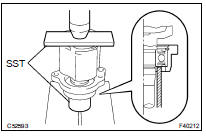
4. REMOVE FRONT AXLE HUB LH NUT
(a) Using SST and a hammer, unstake the staked part of the axle hub LH nut.
SST 09930-00010
NOTICE: Loosen the staked part of the nut completely, otherwise the screw of the drive shaft may be damaged.
(b) While applying the brakes, remove the lock axle hub LH nut.
5. SEPARATE FRONT STABILIZER LINK ASSY LH
(a) Remove the nut, and separate the stabilizer link assy LH.
HINT: If the ball joint turns together with the nut, use a hexagon wrench (6 mm) to hold the stud.
6. SEPARATE SPEED SENSOR FRONT LH
(a) Remove the bolt and clip, and separate the sensor wire and hose from the shock absorber.
NOTICE: Be careful not to damage the speed sensor.
(b) Remove the bolt, and separate the speed sensor front LH from the steering knuckle.
NOTICE: Prevent foreign matter from adhering to the speed sensor.
7. SEPARATE TIE ROD END SUB-ASSY LH
(a) Remove the cotter pin and nut.
(b) Using SST, separate the tie rod end from the steering knuckle.
SST 09628-6201 1
8. SEPARATE FRONT SUSPENSION ARM SUB-ASSY LOWER NO.1 LH
(a) Remove the bolt and 2 nuts, and separate the front suspension arm sub-assy lower No.1 LH from the lower ball joint.
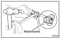
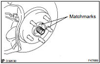
9. SEPARATE FRONT AXLE ASSY LH
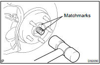
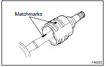
(a) Put matchmarks on the drive shaft and the axle hub.
(b) Using a plastic hammer, separate the drive shaft from the axle hub.
NOTICE: Be careful not to damage the boot and speed sensor rotor.
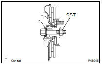
10. REMOVE FRONT DRIVE SHAFT ASSY LH
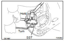
(a) Using SST, remove the front drive shaft assy LH.
SST 09520-01010, 09520-24010 (09520-32040)
NOTICE:
- Be careful not to damage the transaxle case oil seal, inboard joint boot and drive shaft dust cover.
- Be careful not to drop the drive shaft assy.
11. REMOVE FRONT DRIVE SHAFT ASSY RH (3MZ-FE for 2WD DRIVE TYPE)
(a) Using a screwdriver, remove the bearing bracket hole snap ring.
(b) Remove the bolt and front drive shaft assy RH from the drive shaft bearing bracket
12. REMOVE FRONT DRIVE SHAFT ASSY RH (2AZ-FE for 2WD DRIVE TYPE)
(a) Remove the 2 bolts and pull out the drive shaft together with the center bearing bracket.
(b) Remove the drive shaft assy RH.
13. REMOVE FRONT DRIVE SHAFT ASSY RH (RH for 4WD DRIVE TYPE)
SST 09520-01010, 09520-24010 (09520-32040) HINT: Overhaul the RH side following the same procedures as for the LH side.
NOTICE:
- When removing and installing the front drive shaft assy RH in a 4WD vehicle, be sure to first drain all the transaxle oil and transfer oil. If removal and installation is carried out without draining these oils, the transfer oil will flow into the transaxle side. Extensive cleaning will be required if the two oils mix.
- Do not damage the oil seal and dust cover.
- Move the drive shaft assy while keeping it level.
14. FIX FRONT AXLE ASSY LH
SST 09608-16042 (09608-02021, 09608-02041)
NOTICE:
- The hub bearing could be damaged if it is subjected to the vehicle's full weight, such as when moving the vehicle with the drive shaft removed.
- Therefore, if it is absolutely necessary to place the vehicle weight on the hub bearing, first support it with SST.
15. INSPECT FRONT DRIVE SHAFT ASSY LH
(a) Check that there is no remarkable play in the radial direction of the outboard joint.
(b) Check that the inboard joint slides smoothly in the thrust direction.
(c) Check that there is no remarkable play in the radial direction of the inboard joint.
(d) Check the boots for damage.
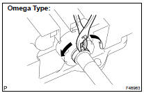
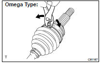
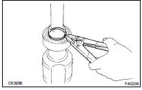
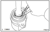
16. REMOVE FRONT AXLE INBOARD JOINT BOOT LH NO.2 CLAMP
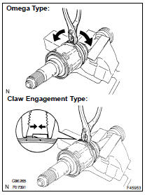
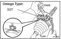
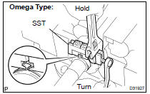
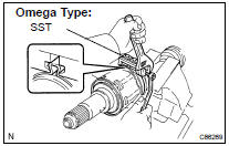
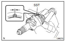
(a) Omega Type: Using pliers, remove the inboard joint boot LH No.2 clamp, as shown in the illustration.
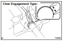
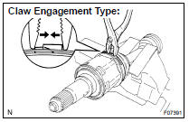
(b) Claw Engagement Type: Using pliers, remove the inboard joint boot LH No.2 clamp, as shown in the illustration.
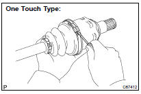
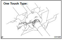
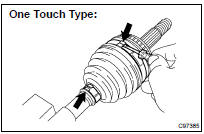
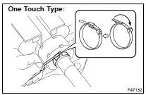
(c) One Touch Type: Using a screwdriver, remove the inboard joint boot LH No.2 clamp, as shown in the illustration.
17. REMOVE FRONT AXLE INBOARD JOINT BOOT LH CLAMP
(a) Remove the inboard joint boot LH clamp using the same procedures as for the inboard joint boot LH No.2 clamp.
18. SEPARATE FR AXLE INBOARD JOINT BOOT
(a) Separate the inboard joint boot from the inboard joint assy.
19. REMOVE FRONT DRIVE INBOARD JOINT ASSY LH
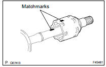
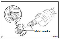
(a) Put matchmarks on the inboard joint assy and outboard joint shaft.
NOTICE: Do not use a punch for the marks.
(b) Remove the inboard joint assy from the outboard joint shaft.
(c) Using a snap ring expander, remove the shaft snap ring.
(d) Put matchmarks on the outboard joint shaft and tripod joint.
NOTICE: Do not use a punch for the marks.
(e) Using a brass bar and hammer, remove the tripod joint from the outboard joint shaft.
NOTICE: Do not tap the roller.
20. REMOVE FRONT DRIVE SHAFT DAMPER LH
HINT: This procedure is unnecessary for a 3MZ-FE 4WD drive type vehicle (Front drive shaft RH) because it dose not have a drive shaft damper.
(a) Omega Type: Using pliers, remove the drive shaft damper clamp, as shown in the illustration.
(b) Claw Engagement: Using needle-nose pliers, remove the drive shaft damper clamp, as shown in the illustration.
(c) One Touch Type: Using a screwdriver, remove the drive shaft damper clamp, as shown in the illustration.
(d) Remove the drive shaft damper.
21. REMOVE FRONT AXLE OUTBOARD JOINT BOOT LH NO.2 CLAMP
(a) Omega Type: Using pliers, remove the outboard joint boot LH No.2 clamp, as shown in the illustration.
(b) One Touch Type: Using a screwdriver, remove the outboard joint boot LH No.2 clamp, as shown in the illustration.
22. REMOVE FRONT AXLE OUTBOARD JOINT BOOT LH CLAMP
(a) Remove the outboard joint boot LH clamp using the same procedures as for the outboard joint boot LH No.2 clamp.
23. REMOVE OUTBOARD JOINT BOOT
(a) Remove the outboard joint boot from the outboard joint shaft.
(b) Remove the old grease from the outboard joint.
24. REMOVE FRONT DRIVE INNER SHAFT INNER LH SHAFT SNAP RING
(a) Using a screwdriver, remove the hole snap ring.
25. REMOVE FRONT DRIVE INNER SHAFT INNER RH SHAFT SNAP RING (RH for 4WD DRIVE TYPE)
(a) Using a screwdriver, remove the hole snap ring.
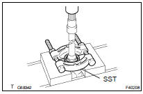
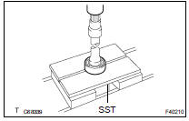
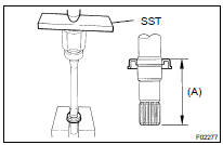
26. REMOVE FRONT DRIVE SHAFT DUST COVER LH
(a) Using SST and a press, remove the drive shaft dust cover LH.
SST 09950-00020
NOTICE: Be careful not to drop the inboard joint assy.
27. REMOVE FRONT DRIVE SHAFT DUST COVER RH (RH for 2WD DRIVE TYPE)
(a) Using a press, remove the drive shaft dust cover RH.
28. REMOVE FRONT DRIVE SHAFT DUST COVER RH (RH for 4WD DRIVE TYPE)
(a) Using SST and a press, remove the drive shaft dust cover RH.
SST 09950-00020
29. REMOVE FRONT DRIVE SHAFT DUST COVER (RH for 2WD DRIVE TYPE)
(a) Using SST and a press, remove the drive shaft dust cover.
SST 09950-00020
30. REMOVE CASE SUB ASSY, DRIVE SHAFT BEARING SNAP RING (2AZ-FE for 2WD DRIVE TYPE)
(a) Using a screwdriver, remove the bearing case snap ring.
31. REMOVE DRIVE SHAFT BEARING CASE SUB ASSY (2AZ-FE for 2WD DRIVE TYPE)
(a) Using a press, remove the bearing case snap ring.
NOTICE: Be careful not to drop the inboard joint assy.
32. REMOVE FRONT DRIVE SHAFT BEARING (RH for 2WD DRIVE TYPE)
(a) Using a snap ring expander, remove the drive shaft hole snap ring.
(b) Using SST and a press, remove the bearing.
SST 09527-1001 1
(c) Remove the bearing bracket hole snap ring.
NOTICE: Be careful not to drop the inboard joint assy.
33. INSTALL FRONT DRIVE SHAFT BEARING (3MZ-FE for 2WD DRIVE TYPE)
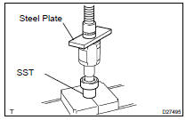
(a) Install a new bearing bracket hole snap ring to the front driver shaft assy RH.
(b) Using SST and a steel plate, install a new front drive shaft bearing.
SST 09710-30021 (09710-03141)
NOTICE: Bearing should be completely installed.
(c) Using a snap ring expander, install a new drive shaft hole snap ring.
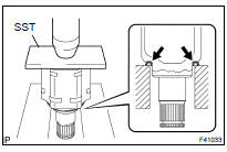
34. INSTALL FRONT DRIVE SHAFT DUST COVER (3MZ-FE for 2WD DRIVE TYPE)
(a) Using SST and a press, install a new drive shaft dust cover.
SST 09726-40010, 09527-10011
NOTICE:
- Dust cover should be completely installed.
- Be careful not to damage the dust cover.
35. INSTALL FRONT DRIVE SHAFT BEARING (2AZ-FE for 2WD DRIVE TYPE)
(a) Using SST and a press, install a new drive shaft bearing.
SST 09950- 60020 (09951- 00710), 09950- 70010 (09951-07100)
36. INSTALL CASE SUB ASSY, DRIVE SHAFT BEARING SNAP RING (2AZ-FE for 2WD DRIVE TYPE)
(a) Using a screwdriver, install a new bearing case snap ring.
37. INSTALL DRIVE SHAFT BEARING CASE SUB ASSY (2AZ-FE for 2WD DRIVE TYPE)
(a) Using SST and a press, install the drive shaft bearing case to the inboard joint assy RH.
SST 09527-1001 1, 09710-04081
NOTICE: Bearing should be installed completely.
(b) Using a snap ring expander, install a new drive shaft hole snap ring.
38. INSTALL FRONT DRIVE SHAFT DUST COVER (2AZ-FE for 2WD DRIVE TYPE)
(a) Using SST and a press, install a new driver shaft dust cover.
SST 09726-40010, 09527-10011 Distance (A): 0.5 0.5 mm (0.020 0.020 in.)
NOTICE: Be careful not to damage the dust cover.
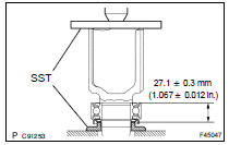
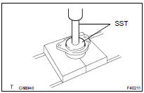
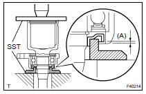
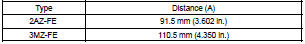
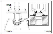
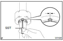
39. INSTALL FRONT DRIVE SHAFT DUST COVER RH (RH for 2WD DRIVE TYPE)
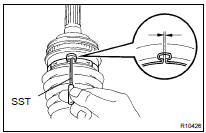
(a) Using SST and a press, install a new drive shaft dust cover RH until the distance from the tip of the center drive shaft to the drive shaft dust cover RH meets the specification, as shown in the illustration.
SST 09527-1001 1
NOTICE:
- Dust cover should be completely installed.
- Be careful not to damage the dust cover.
40. INSTALL FRONT DRIVE SHAFT DUST COVER RH (RH for 4WD DRIVE TYPE)
(a) Using SST and a press, install a new drive shaft dust cover RH.
SST 09527-1001 1
NOTICE:
- Dust cover should be completely installed.
- Be careful not to damage the dust cover.
41. INSTALL FRONT DRIVE SHAFT DUST COVER LH
(a) Using SST and a press, install a new drive shaft dust cover LH.
SST 09527-1001 1
NOTICE:
- Dust cover should be completely installed.
- Be careful not to damage the dust cover.
42. INSTALL FRONT DRIVE INNER SHAFT INNER LH SHAFT SNAP RING
(a) Install a new hole snap ring.
43. INSTALL FRONT DRIVE INNER SHAFT INNER RH SHAFT SNAP RING (RH for 4WD DRIVE TYPE)
(a) Install a new hole snap ring.
44. INSTALL OUTBOARD JOINT BOOT
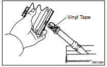
HINT: Before installing the boots, wrap the spline of the drive shaft with vinyl tape to prevent the boots from being damaged.
(a) Hold the drive shaft lightly in a soft vise.
(b) Temporarily install a new outboard joint boot with 2 clamps to the drive shaft.
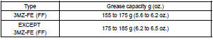
(c) Pack the outboard joint shaft and boot with grease.
45. INSTALL FRONT AXLE OUTBOARD JOINT BOOT LH NO.2 CLAMP
(a) Omega Type: Secure the 2 outboard joint boot clamps onto the boot.
(b) Place SST onto the outboard joint boot LH No.2 clamp.
SST 09521-24010
(c) Tighten the SST so that the outboard joint boot LH No.2
clamp is pinched.
NOTICE: Do not overtighten the SST.
(d) Using SST, measure the clearance of the outboard joint boot LH No.2 clamp.
SST 09240-00020
Clearance: 0.8 mm (0.031 in.) or less
NOTICE: When the measured value is greater than the specified value, retighten the clamp.
46. INSTALL FRONT AXLE OUTBOARD JOINT BOOT LH CLAMP
(a) The procedure for the outboard joint boot LH clamp is the same as above.
SST 09521-24010, 09240-00020
47. INSTALL FRONT DRIVE SHAFT DAMPER LH
(a) Install the drive shaft damper LH to the drive shaft.
(b) Make sure that the damper is on the shaft groove.
(c) Set the distance, as described below.
48. INSTALL FRONT DRIVE SHAFT DAMPER RH CLAMP
(a) Omega Type: Hold the front drive shaft lightly in a soft vise.
(b) Install the drive shaft damper clamp to the damper.
NOTICE: Be sure to install the clamp in the correct position.
(c) Place SST onto the drive shaft damper clamp.
SST 09521-24010
(d) Tighten the SST so that the clamp is pinched.
NOTICE: Do not overtighten the SST.
(e) Using SST, measure the clearance of the drive shaft damper clamp.
SST 09240-00020
Clearance: 0.8 mm (0.031 in.) or less
NOTICE: When the measured value is greater than the specified value, retighten the clamp.
HINT: This procedure is unnecessary for a 3MZ-FE 4WD drive type vehicle (Front drive shaft RH) because it dose not have a drive shaft damper.
(f) One Touch Type: Set a new damper clamp to the drive shaft damper RH and install the damper clamp with a screwdriver.
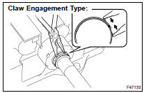
(g) Claw Engagement Type: Set a new damper clamp to the drive shaft damper RH and install the damper clamp with needle-nose pliers.
49. INSTALL FRONT DRIVE INBOARD JOINT ASSY LH
(a) Temporarily install a new inboard joint boot with 2 clamps to the drive shaft.
(b) Place the beveled side of the tripod joint axial spline toward the outboard joint shaft.
(c) Align the matchmarks.
(d) Using a brass bar and hammer, tap in the tripod joint to the outboard joint shaft.
NOTICE:
- Do not tap the roller.
- Be sure to install the tripod joint assy in the correct direction.
(e) Using a snap ring expander, install a new shaft snap ring.
(f) Pack the outboard joint shaft and boot with grease.
(g) Align the matchmarks, install the inboard joint assy to the outboard joint shaft assy.
50. INSTALL FR AXLE INBOARD JOINT BOOT
(a) Install the inboard joint boot to the inboard joint assy.
51. INSTALL FRONT AXLE INBOARD JOINT BOOT LH CLAMP
(a) Omega Type: Install new inboard joint boot clamps.
- Hold the drive shaft lightly in a soft vise.
- Install 2 new inboard joint boot clamps to the boot
- ) Place SST onto the inboard joint boot LH No.2
clamp.
SST 09521-24010
- Tighten the SST so that the inboard joint boot LH No.2 clamp is pinched.
NOTICE: Do not overtighten the SST.
- Using SST, measure the clearance of the inboard joint boot LH No.2 clamp.
SST 09240-00020
Clearance: 0.8 mm (0.031 in.) or less
NOTICE: When the measured value is greater than the specified value, retighten the clamp.
(b) Claw Engagement Type: Using pliers, install the inboard joint boot LH No.2 clamp, as shown in the illustration.
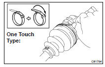
(c) One Touch Type: Using a screwdriver, install the inboard joint boot LH No.2 clamp, as shown in the illustration.
52. INSTALL FRONT AXLE INBOARD JOINT BOOT LH CLAMP
(a) Install the inboard joint boot LH clamp using the same procedures as for the inboard joint boot LH No.2 clamp.
SST 09521-24010, 09240-00020
53. INSPECT FRONT DRIVE SHAFT
(a) Check that there is no remarkable play in the radial direction of the outboard joint.
(b) Check that the inboard joint slides smoothly in the thrust direction.
(c) Check that there is no remarkable play in the radial direction of the inboard joint.
(d) Check the boots for damage.
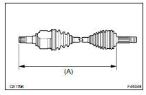
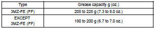
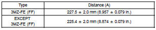
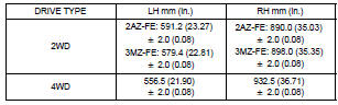
HINT: For dimension (A), refer to the following table.
54. INSTALL FRONT DRIVE SHAFT ASSY LH
(a) Coat the spline of the inboard joint shaft assy with ATF.
(b) Align the shaft splines and install the drive shaft assy with a brass bar and a hammer.
NOTICE:
- Set the snap ring with the opening side facing downward.
- Be careful not to damage the oil seal boot and dust cover.
- Move the drive shaft assy while keeping it level.
55. INSTALL FRONT DRIVE SHAFT ASSY RH (3MZ-FE for 2WD DRIVE TYPE)
(a) Using a screwdriver, install a new bearing bracket hole snap ring.
NOTICE: Do not damage the oil seal and boot.
(b) Install the bolt.
Torque: 32 NVm (330 kgfVcm, 24 ftVlbf)
56. INSTALL FRONT DRIVE SHAFT ASSY RH (2AZ-FE for 2WD DRIVE TYPE)
(a) Coat the spline of the inboard joint shaft assy RH with gear oil.
(b) Align the shaft splines and install the drive shaft assy RH with the 2 bolts.
NOTICE: Do not damage the oil seal, boot and dust cover.
57. INSTALL FRONT DRIVE SHAFT ASSY RH (RH for 4WD DRIVE TYPE)
HINT: Install the RH side using the same procedures as for the LH side.
NOTICE:
- Set the snap ring with the opening side facing downward.
- Be careful not to damage the transaxle case oil seal, inboard joint boot and drive shaft dust cover.
58. INSTALL FRONT AXLE ASSY LH
(a) Align the matchmarks and install the drive shaft assy LH to the front axle assy LH.
NOTICE: Be careful not to damage the outboard joint boot.
Be careful not to damage the speed sensor rotor.
59. INSTALL FRONT SUSPENSION ARM SUB- ASSY LOWER NO.1 LH
(a) Install the lower ball joint to the front suspension arm subassy lower with the bolt and nuts.
Torque: 127 NVm (1,300 kgfVcm, 94 ftVlbf)
60. INSTALL TIE ROD END SUB-ASSY LH
(a) Install the tie rod end to the steering knuckle with the nut.
Torque: 49 NVm (500 kgfVcm, 36 ftVlbf)
(b) Install a new cotter pin.
NOTICE: If the holes for the cotter pin are not aligned, tighten the nut up to 60 further.
61. INSTALL SPEED SENSOR FRONT LH
(a) Install the speed sensor to the steering knuckle with the bolt.
Torque: 8.0 NVm (82 kgfVcm, 71 in.Vlbf)
NOTICE: Prevent foreign matter from adhering to the speed sensor.
(b) Install the flexible hose and the speed sensor to the shock absorber with the bolt and set the clip of the sensor on the knuckle.
Torque: 19 NVm (192 kgfVcm, 14 ftVlbf)
NOTICE:
- Be careful not to damage the speed sensor.
- Prevent foreign matter from adhering to the speed sensor.
- Do not twist the sensor wire when installing the speed sensor.
62. INSTALL FRONT STABILIZER LINK ASSY LH
(a) Install the stabilizer link assy LH with the nut.
Torque: 74 NVm (755 kgfVcm, 55 ftVlbf)
HINT: If the ball joint turns together with the nut, use a hexagon (6 mm) wrench to hold the stud.
63. INSTALL FRONT AXLE HUB LH NUT
(a) Using a socket wrench (30 mm), install a new axle hub LH nut.
Torque: 294 NVm (3,000 kgfVcm, 217 ftVlbf)
(b) Using a chisel and a hammer, stake the axle hub LH nut.
64. INSTALL FRONT WHEEL
Torque: 103 NVm (1,050 kgfVcm, 76 ftVlbf)
65. ADD AUTOMATIC TRANSAXLE FLUID
66. INSPECT AUTOMATIC TRANSAXLE FLUID (SEE PAGE 40-2 )
67. ADD TRANSFER OIL (4WD DRIVE TYPE)
HINT: Perform the procedure only when installing the RH side.
68. INSPECT TRANSFER OIL (4WD DRIVE TYPE) (SEE PAGE 31-4 )
HINT: Perform the procedure only when installing the RH side.
69. INSPECT AND ADJUST FRONT WHEEL ALIGNMENT (SEE PAGE 26-7 )
70. CHECK ABS SPEED SENSOR SIGNAL (SEE PAGE 05-765 )
 Propeller W/Center bearing shaft Propeller w/center bearing shaft
OVERHAUL
HINT:
COMPONENTS:SEE PAGE 30-4
1. REMOVE EXHAUST PIPE ASSY
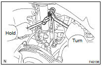
2. REMOVE PROPELLER W/CENTER BEARING SHAFT ASSY
(a) Depress the brake pedal and hold it.
(b) Using a hexagon wrench (6 mm) ...
 Front axle hub sub-ASSY LH
REPLACEMENT
HINT:
COMPONENTS: SEE PAGE 30-4
Replace the RH side by the same procedures with LH side.
1. REMOVE FRONT WHEEL
2. REMOVE FRONT AXLE HUB LH NUT
(a) Using SST and a hammer, unstake ...
More about Toyota Highlander:
Parking brake
Operating instructions
To set the parking brake, fully
depress the parking brake pedal
with your left foot while depressing
the brake pedal with your right
foot.
(Depressing the pedal again
releases the parking brake.)
*1: For u.S.A.
*2: For canada
Parking brake engaged warning buzze ...
