Toyota Highlander Service Manual: Front wheel alignment
ADJUSTMENT
1. INSPECT TIRE (SEE PAGE 26-7 )
2. MEASURE VEHICLE HEIGHT
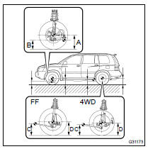
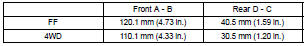
Vehicle height:
Measuring points:
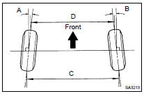
A: Ground clearance of front wheel center
B: Ground clearance of lower suspension arm No.2 bush
set bolt center
C: Ground clearance of strut rod set bolt center
D: Ground clearance of rear wheel center
NOTICE: Before inspecting the wheel alignment, adjust the vehicle height to the specified value.
HINT: Bounce the vehicle at the corners up and down to stabilize the suspension and inspect the vehicle height.
3. INSPECT TOE-IN
Toe-in:

If the toe-in is not within the specified range, adjust it at the rack ends.
4. ADJUST TOE-IN
(a) Remove the rack boot set clips.
(b) Loosen the tie rod end lock nuts.
(c) Turn the right and left rack ends by equal amounts to adjust the toe-in.
HINT: Try to adjust the toe-in to the center of the specified value.
(d) Make sure that the lengths of the right and left rack ends are the same.
Rack and length difference: 1.5 mm (0.059 in.) or less (e) Torque the tie rod end lock nuts.
Torque: 74 N*m (755 kgf*cm, 55 ft*lbf) (f) Place the boots on the seats and install the clips.
HINT: Make sure that the boots are not twisted.
(g) Perform VSC system calibration (see page 05-765 ).
5. INSPECT WHEEL ANGLE
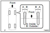
(a) Turn the steering wheel fully left and right to measure the turning angle.
Wheel turning angle:
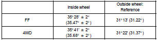
If the right and left inside wheel angles differ from the specified value, check and adjust the right and left rack end lengths.
6. INSPECT CAMBER, CASTER AND STEERING AXIS INCLINATION
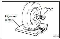
(a) Put the front wheel on the center of the alignment tester.
(b) Set the camber - caster - kingpin gauge at the center of the axle hub or drive shaft.
Camber, caster and steering axis inclination:
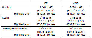
If the caster and steering axis inclination are not within the specified values after the camber has been correctly adjusted, recheck the suspension parts for damage and/or wear.
7. ADJUST CAMBER
NOTICE: Inspect toe-in after the camber has been adjusted.
(a) Remove the front wheel.
(b) Remove the 2 nuts on the lower side of the shock absorber.
HINT: When removing the nuts, keep the bolts from rotating.
(c) Clean the installation surface of the shock absorber and the steering knuckle.
(d) Temporarily install the 2 nuts.
(e) Fully push or pull the front axle hub in the direction of the required adjustment.
(f) Tighten the nuts.
Torque: 230 NVm (2,350 kgfVcm, 170 ftVlbf) HINT: When installing the nuts, keep the bolts from rotating and then torque the nuts.
(g) Install the front wheel.
Torque: 103 N*m (1,050 kgf*cm, 76 ft*lbf)
NOTICE: Keep the bolts from rotating and torque the nuts.
(h) Install the front wheel.
Torque: 103 NVm (1,050 kgfVcm, 76 ftVlbf) (i) Check the camber.
If the measured value is not within the specified range, calculate the required adjustment amount using the formula below.
(Camber adjustment amount) = Center of the specified range medium - Measured value
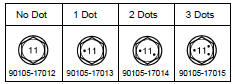
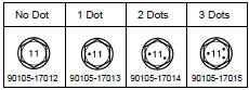
Check installed bolts combination. Select appropriate bolts from the table below to adjust the camber to within the specified range.
|
Move the axle toward (+) in step (e) |
Refer to table (1) (Move the axle toward positive side) |
|
Move the axle toward (-) in step (e) |
Refer to table (2) (Move the axle toward negative side) |
Table (1) (Move the axle toward positive side)
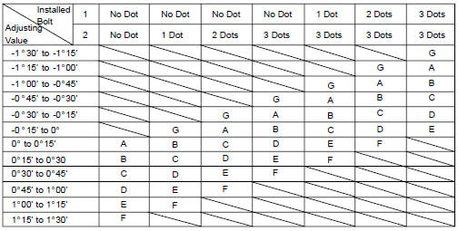
Selected Bolt Combination
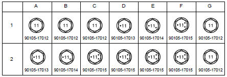
Bolt Distinguishing Mark
The body and suspension may be damaged if the camber is not correctly adjusted according to the above table.
NOTICE: Replace the nut with a new one when replacing the bolt.
(j) Repeat the steps mentioned above. At step (b), replace 1 or 2 selected bolts.
HINT: Replace one bolt at a time when replacing 2 bolts.
Table (2) (Move the axle toward negative side)
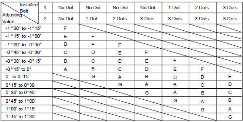
Selected Bolt Combination
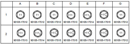
Bolt Distinguishing Mark
The body and suspension may be damaged if the camber is not correctly adjusted according to the above table.
NOTICE: Replace the nut with a new one when replacing the bolt.
(k) Repeat the steps mentioned above. At step (b), replace 1 or 2 selected bolts.
HINT: Replace one bolt at a time when replacing 2 bolts.
 Front suspension
SUSPENSION
...

More about Toyota Highlander:
Transfer oil (4WD)
ADJUSTMENT
1. REMOVE EXHAUST PIPE ASSY FRONT (3MZ-FE ENGINE TYPE) (SEE PAGE 15-5 )
2. REMOVE EXHAUST PIPE ASSY FRONT (2AZ-FE ENGINE TYPE) (SEE PAGE 15-2 )
3. INSPECT TRANSFER OIL
(a) Remove the No.1 plug and gasket.
(b) Check the oil level is within 0 to 5 mm (0 to 0.1968 in.)
down from th ...
