Toyota Highlander Service Manual: Replacement
1. REMOVE FRONT WHEEL RH
2. REMOVE ENGINE UNDER COVER NO.1
3. REMOVE FRONT FENDER APRON SEAL RH
4. DRAIN ENGINE OIL
(a) Install a new gasket and the drain plug after draining engine oil.
Torque: 25 NVm (255 kgfVcm, 18 ftVlbf)
5. REMOVE EXHAUST PIPE ASSY FRONT
6. REMOVE ENGINE MOVING CONTROL ROD W/BRACKET (See page 14-24 )
7. REMOVE ENGINE MOUNTING STAY NO.2 RH (See page 14-24 )
8. REMOVE ENGINE MOUNTING BRACKET NO.2 RH (See page 14-24 )
9. REMOVE FAN AND GENERATOR V BELT (See page 14-5 )
10. REMOVE ENGINE COVER SUB-ASSY NO.1
11. DISCONNECT ENGINE WIRE
12. REMOVE GENERATOR ASSY
13. REMOVE VANE PUMP ASSY (See page 51-8 )
NOTICE: Do not disconnect the hose.
14. REMOVE IGNITION COIL ASSY
15. DISCONNECT VENTILATION HOSE
16. DISCONNECT VENTILATION HOSE NO.2
17. REMOVE CYLINDER HEAD COVER SUB-ASSY (See page 14-41 )
18. SET NO. 1 CYLINDER TO TDC/COMPRESSION (See page 14-6 )
19. REMOVE CRANKSHAFT PULLEY (See page 14-41 )
20. REMOVE CRANKSHAFT POSITION SENSOR (See page 14-41 )
21. REMOVE OIL PAN SUB-ASSY
(a) Remove the 12 bolts and 2 nuts.
(b) Insert the blade of SST between the crankcase and oil pan. Cut through the sealer and remove the oil pan.
SST 09032-00100
NOTICE: Be careful not to damage the contact surface of the cylinder block and oil pan.
22. REMOVE CHAIN TENSIONER ASSY NO.1 (See page 14-41 )
23. REMOVE V-RIBBED BELT TENSIONER ASSY (See page 14-24 )
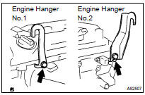
24. INSTALL ENGINE HANGER NO.1
25. REMOVE ENGINE MOUNTING INSULATOR
(a) Attach the engine chain hoist to the engine hangers.
CAUTION: Do not attempt to hang the engine by hooking the chain to any other part.
(b) Remove the bolt and disconnect the engine mounting insulator FR.
(c) Remove the bolt and disconnect the steering gear return hose clamp from the frame.
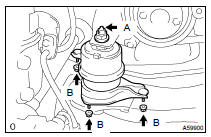
(d) Remove the 4 nuts from the engine mounting insulator RH.
(e) Raise the engine and remove the engine mounting insulator RH.
26. REMOVE ENGINE MOUNTING BRACKET RH
(a) Remove the 3 bolts and engine mounting bracket.
27. REMOVE TIMING CHAIN OR BELT COVER SUB-ASSY (See page 14-41 )
28. REMOVE CRANKSHAFT POSITION SENSOR PLATE NO.1
29. REMOVE CHAIN TENSIONER SLIPPER (See page 14-68 )
30. REMOVE CHAIN VIBRATION DAMPER NO.1 (See page 14-68 )
31. REMOVE CHAIN SUB-ASSY (See page 14-68 )
32. REMOVE CRANKSHAFT TIMING GEAR OR SPROCKET
33. REMOVE NO.2 CHAIN SUB-ASSY
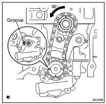
(a) Turn the crankshaft counterclockwise 90 , and align the adjusting hole of the oil pump drive sprocket gear with the groove of the oil pump.
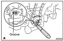
(b) Insert a bar (f 4.0 mm (0.16 in.)) into the adjusting hole of the oil pump drive sprocket to temporarily lock the sprocket in position. Remove the nut.
(c) Remove the bolt, chain tensioner plate and spring.
(d) Remove the chain tensioner, oil pump drive sprocket and chain.
34. REMOVE OIL PUMP ASSY
(a) Remove the 3 bolts, oil pump and gasket.
35. INSTALL OIL PUMP ASSY
(a) Install a new gasket and oil pump with the 3 bolts.
Torque: 19 NVm (194 kgfVcm, 14 ftVlbf)
36. INSTALL NO.2 CHAIN SUB-ASSY
(a) Set the crankshaft key in the horizontal left position.
(b) Turn the cutout of the drive shaft to the top.
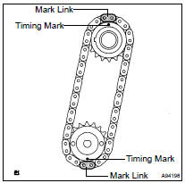
(c) Align the mark links (yellow colored links) of the chain with the timing marks of the gear as shown in the illustration.
(d) Insert the gear together with chain into the crankshaft and oil pump shaft.
(e) Temporarily tighten the oil pump drive shaft gear with the nut.
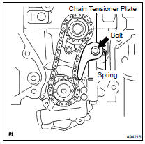
(f) Insert the damper spring into the adjusting hole, and install the chain tensioner plate with the bolt.
Torque: 12 NVm (122 kgfVcm, 9 ftVlbf)
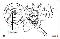
(g) Align the adjusting hole of the sprocket with the groove of the oil pump.
(h) Insert a bar (f 4 mm (0.16 in.)) into the adjusting hole of the sprocket to temporarily lock the gear in position. Install the nut.
Torque: 30 NVm (306 kgfVcm, 22 ftVlbf)
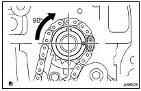
(i) Rotate the crankshaft 90 clockwise and align the crankshaft key with the top.
37. INSTALL CRANKSHAFT TIMING GEAR OR SPROCKET
38. INSTALL CHAIN VIBRATION DAMPER NO.1
(a) Install the chain vibration damper with the 2 bolts.
Torque: 9.0 NVm (92 kgfVcm, 80 in.Vlbf)
39. INSTALL CHAIN SUB-ASSY (See page 14-68 )
40. INSTALL CRANKSHAFT POSITION SENSOR PLATE NO.1 (See page 14-41 )
41. INSTALL TIMING CHAIN OR BELT COVER SUB-ASSY (See page 14-41 )
42. INSTALL V-RIBBED BELT TENSIONER ASSY (See page 14-24 )
43. INSTALL ENGINE MOUNTING BRACKET RH
(a) Install the engine mounting bracket with the 3 bolts.
Torque: 54 NVm (551 kgfVcm, 40 ftVlbf)
44. INSTALL ENGINE MOUNTING INSULATOR
(a) Raise the engine and install the engine mounting insulator RH.
(b) Install the engine mounting insulator RH with the 4 nuts.
Torque: 95 NVm (969 kgfVcm, 70 ftVlbf) for nut A 87 NVm (887 kgfVcm, 64 ftVlbf) for nut B
(c) Install the steering gear return hose clamp to the frame with the bolt.
Torque: 8.0 NVm (82 kgfVcm, 71 in.Vlbf)
(d) Install the engine mounting insulator FR with the bolt.
Torque: 87 NVm (887 kgfVcm, 64 ftVlbf)
45. INSTALL OIL PAN SUB-ASSY
NOTICE:
- Remove any oil from the contact surface.
- Install the oil pan within 3 minutes after applying seal packing.
- Do not start the engine for at least 2 hours after installing.
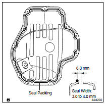
(a) Remove any old packing (FIPG) material and be careful not to drop any oil on the contact surfaces of the cylinder block and oil pan.
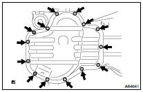
(b) Apply seal packing in a continuous bead (Seal Width: 3.0 to 4.0 mm (0.12 to 0.16 in.)) as shown in the illustration, and install the oil pan.
Seal packing: Part No. 08826-00080 or equivalent
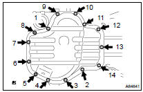
(c) Uniformly tighten the 12 bolts and 2 nuts in the sequence shown in the illustration.
Torque: 9.0 NVm (92 kgfVcm, 80 in.Vlbf)
46. INSTALL CRANKSHAFT POSITION SENSOR (See page 14-41 )
47. INSTALL CRANKSHAFT PULLEY (See page 14-41 )
48. INSTALL CHAIN TENSIONER ASSY NO.1 (See page 14-68 )
49. INSTALL CYLINDER HEAD COVER SUB-ASSY
50. INSTALL IGNITION COIL ASSY
51. INSTALL VANE PUMP ASSY
52. INSTALL GENERATOR ASSY
53. INSTALL ENGINE WIRE
54. INSTALL FAN AND GENERATOR V BELT (See page 14-5 )
55. INSTALL ENGINE MOUNTING BRACKET NO.2 RH
56. INSTALL ENGINE MOUNTING STAY NO.2 RH
57. INSTALL ENGINE MOVING CONTROL ROD W/BRACKET (See page 14-24 )
58. INSTALL EXHAUST PIPE ASSY FRONT (See page 15-2 )
59. INSTALL FRONT WHEEL RH
60. ADD ENGINE OIL
61. CHECK FOR ENGINE OIL LEAKS
 Components
...
 Overhaul
1. REMOVE OIL PUMP STRAINER SET
(a) Remove the 2 nuts and oil pump strainer.
2. REMOVE OIL PUMP RELIEF VALVE
(a) Using a socket wrench (27 mm), remove the plug.
(b) Remove the valve spring ...
More about Toyota Highlander:
Rear heater blower switch
REPLACEMENT
HINT:
Installation is in the reverse order of removal.
1. REMOVE DECK SIDE TRIM COVER FRONT LH
(a) Using a thin flat-head screwdriver with the tip taped up
with protective tape, disengage the 2 claw fittings and remove
the deck side trim cover front.
2. REMOVE DECK SIDE TRIM C ...
