Toyota Highlander Service Manual: Replacement
1. WORK FOR PREVENTING GASOLINE FROM SPILLING OUT (See page 11-35 )
2. REMOVE FRONT WHEELS
3. REMOVE ENGINE UNDER COVER NO.1
4. REMOVE FRONT FENDER SPLASH SHIELD SUB-ASSY LH
5. REMOVE FRONT FENDER SPLASH SHIELD SUB-ASSY RH
6. REMOVE FRONT FENDER APRON SEAL LH
7. REMOVE FRONT FENDER APRON SEAL RH
8. DRAIN ENGINE OIL
9. DRAIN ENGINE COOLANT (See page 16-26 )
10. DRAIN AUTOMATIC TRANSAXLE FLUID
11. DRAIN TRANSFER OIL (4WD TYPE)
12. REMOVE FR WIPER ARM LH (See page 66-7 )
13. REMOVE FR WIPER ARM RH (See page 66-7 )
14. REMOVE COWL TOP VENTILATOR LOUVER SUB-ASSY (See page 66-7 )
15. REMOVE WINDSHIELD WIPER LINK ASSY (See page 66-7 )
16. REMOVE COWL PANEL SUB-ASSY
17. REMOVE FRONT SUSPENSION BRACE SUB-ASSY UPPER CENTER
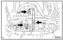
18. REMOVE V-BANK COVER SUB-ASSY

(a) Using a 5 mm hexagon wrench, remove the 3 nuts.
(b) Disconnect the 2 clips, and remove the cover.
19. REMOVE BATTERY
20. REMOVE AIR CLEANER CAP SUB-ASSY
21. REMOVE AIR CLEANER FILTER ELEMENT SUB-ASSY
22. REMOVE AIR CLEANER CASE
23. REMOVE V (COOLER COMPRESSOR TO CRANKSHAFT PULLEY) BELT NO.1 (See page 14-125 )
24. REMOVE VANE PUMP V BELT (See page 14-125 )
25. REMOVE GENERATOR ASSY (See page 19-40 )
26. REMOVE GENERATOR BRACKET NO.2
27. REMOVE GENERATOR BELT ADJUSTING BAR
(a) Remove the 2 bolts, 2 nuts and adjusting bar.
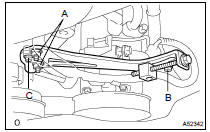
28. REMOVE ENGINE MOVING CONTROL ROD
(a) Remove the 4 bolts and control rod.
29. REMOVE ENGINE MOUNTING STAY NO.2 RH
(a) Remove the bolt, mounting stay No. 2 RH and mounting bracket No. 2 RH.
30. SEPARATE COMPRESSOR AND MAGNETIC CLUTCH
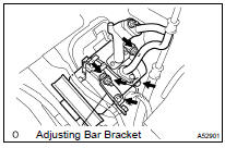
(a) Remove the bolt, nut and adjusting bar bracket.
(b) Remove the 3 bolts and disconnect the compressor.
HINT: Hang up the hoses instead of detaching them.
31. SEPARATE TRANSMISSION CONTROL CABLE ASSY (See page 40-73 )
32. DISCONNECT UNION TO CHECK VALVE HOSE
(a) Remove the vacuum hose for the brake booster.
33. DISCONNECT FUEL PIPE SUB-ASSY NO.1
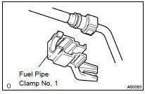
(a) Remove the fuel pipe clamp.
(b) Disconnect the connector from the tube while pinching part A with fingers as shown in the illustration.
NOTICE:
- Check for contamination in the pipe and around the connector. Clean if necessary and then disconnect the connector.
- Disconnect the connector with your hands.
- Do not bend, fold or rotate the nylon tube.
- If the pipe and connector are stuck together, push and pull the connector until it comes free.
- Put the pipe and connector ends in vinyl bags to prevent damage and contamination.
34. DISCONNECT HEATER INLET WATER HOSE
35. DISCONNECT HEATER OUTLET WATER HOSE
36. DISCONNECT RADIATOR HOSE INLET
37. DISCONNECT RADIATOR HOSE OUTLET
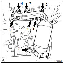
38. DISCONNECT OIL COOLER INLET TUBE NO.1
39. DISCONNECT OIL COOLER OUTLET TUBE NO.1
40. DISCONNECT OIL RESERVOIR TO PUMP HOSE NO.1
41. DISCONNECT STEERING GEAR OUTLET RETURN TUBE
42. REMOVE GLOVE COMPARTMENT DOOR ASSY
43. SEPARATE ENGINE WIRE
(a) Disconnect the engine wire from the ECM and junction block.
(b) Disconnect the engine wire from the engine room junction block.
- Remove the nut and separate the wire harness.
- Using a screwdriver, release the engine room junction block. Disconnect the engine wire by pulling it upward.
(c) Remove the 2 nuts and pull out the engine wire.
(d) Remove the body ground.
44. REMOVE PROPELLER SHAFT ASSY (4WD TYPE) (See page 30-12 )
45. DISCONNECT EXHAUST PIPE SUB-ASSY FRONT NO.3 (See page 15-5 )
46. DISCONNECT EXHAUST PIPE ASSY FRONT (See page 15-5 )
47. REMOVE EXHAUST PIPE SUPPORT BRACKET NO.1 (See page 15-5 )
48. DISCONNECT FRONT STABILIZER LINK ASSY LH
(a) Using a 6 mm socket hexagon wrench, hold the ball stud.
(b) Remove the nut and disconnect the stabilizer link.
49. DISCONNECT FRONT STABILIZER LINK ASSY RH
HINT: Use the same procedures described for the LH side.
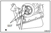
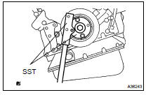
50. REMOVE FRONT AXLE HUB LH NUT
(a) Using SST and a hammer, strike the lock nut covering to remove it.
SST 09930-00010
NOTICE:
- Set the drive shaft's groove so that it faces up. Then use the SST and hammer.
- Remove the covering from the lock nut completely or the screw of the drive shaft may be damaged.
- Do not sharpen the tip of the SST.
(b) Using a 30 mm socket wrench, remove the lock nut.
51. REMOVE FRONT AXLE HUB RH NUT
HINT: Use the same procedures described for the LH side.
52. DISCONNECT SPEED SENSOR FRONT LH
(a) Remove the bolt and disconnect the speed sensor from the steering knuckle.
NOTICE: Keep the speed sensor tip and connection free from foreign matter.
53. DISCONNECT SPEED SENSOR FRONT RH
HINT: Use the same procedures described for the LH side.
54. SEPARATE TIE ROD END SUB-ASSY LH
(a) Remove the cotter pin and nut.
(b) Using SST, disconnect the tie rod end from the steering knuckle.
SST 09628-6201 1
NOTICE: Do not damage the dust cover of the ball joint.
55. SEPARATE TIE ROD END SUB-ASSY RH
HINT: Use the same procedures described for the LH side.
56. SEPARATE FRONT SUSPENSION ARM SUB-ASSY LOWER NO.1 LH
(a) Remove the bolt and 2 nuts, and separate the front suspension arm from the lower ball joint.
(b) Using a plastic hammer, disconnect the drive shaft from the axle hub.
57. SEPARATE FRONT SUSPENSION ARM SUB-ASSY LOWER NO.1 RH
HINT: Use the same procedures described for the LH side.
58. REMOVE DRIVE PLATE & TORQUE CONVERTER CLUTCH SETTING BOLT
(a) Using SST, hold the crankshaft.
SST 09213-54015 (91651-60855), 09330-00021 (b) Remove the 2 bolts and flywheel housing under cover.
(c) Remove the 6 torque converter setting bolts.
59. SEPARATE STEERING INTERMEDIATE SHAFT SUB-ASSY
(a) Loosen the sliding yoke bolt.
(b) Place matchmarks on the steering intermediate shaft and control valve shaft.
(c) Remove the bolt and disconnect the steering intermediate shaft.
(d) To prevent the steering wheel from rotating, fix the wheel with the seat belt.
NOTICE: If the steering wheel is not fixed, the spiral cable will be damaged.
60. REMOVE ENGINE ASSEMBLY WITH TRANSAXLE
(a) Set the engine lifter.
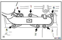
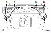
(b) Remove the 6 bolts, 2 nuts, and frame side rail plate subassembly LH and RH.
(c) Remove the 6 bolts, 2 nuts, and front suspension member brace rear LH and RH.
(d) Carefully, remove the engine assembly from the vehicle.
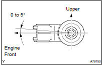
(e) Install the engine hanger as shown in the illustration.
Part No.:
Torque: 20 NVm (204 kgfVcm, 15 ftVlbf)
(f) Using a chain block and an engine sling device, hang the engine assembly
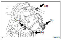
61. REMOVE EXHAUST MANIFOLD CONVERTER SUB-ASSY
(a) Disconnect the A/F sensor connector.
(b) Remove the 3 bolts and insulator.
(c) Uniformly loosen and remove the 6 nuts in the sequence shown in the illustration.
(d) Remove the manifold and gasket.
62. INSPECT EXHAUST MANIFOLD CONVERTER SUB-ASSY
(a) Using a precision straight edge and feeler gauge, measure the surface contacting the cylinder head for warpage.
Maximum warpage: 0.50 mm (0.0196 in.)
If the warpage is greater than the maximum, replace the manifold.
63. REMOVE VANE PUMP ASSY
(a) Remove the power steering oil pressure sensor harness.
(b) Remove the pressure feed tube clamp.
(c) Remove the 2 bolts and vane pump.
64. REMOVE STABILIZER BAR FRONT (See page 26-22 )
65. REMOVE POWER STEERING LINK ASSY (See page 51-28 )
66. REMOVE FRONT FRAME ASSY
(a) Remove the 2 nuts and disconnect the engine mounting insulator RH and LH.
(b) Remove the nut and disconnect the engine mounting insulator FR.
(c) Remove the 2 bolts and disconnect the engine mounting insulator RR.
67. REMOVE FRONT DRIVE SHAFT ASSY LH (See page 30-21 )
68. REMOVE FRONT DRIVE SHAFT ASSY RH (2WD TYPE) (See page 30-21 )
69. REMOVE FRONT DRIVE SHAFT ASSY RH (4WD TYPE) (See page 30-21 )
70. REMOVE STARTER ASSY (See page 19-28 )
71. REMOVE ENGINE MOUNTING BRACKET FR
72. REMOVE AUTOMATIC TRANSAXLE ASSY (2WD TYPE) (See page 40-20 )
73. REMOVE TRANSFER STIFFENER PLATE RH (4WD TYPE)
74. REMOVE AUTOMATIC TRANSAXLE W/TRANSFER (4WD TYPE) (See page 40-20 )
75. REMOVE ENGINE MOUNTING BRACKET RR
76. REMOVE DRIVE PLATE & RING GEAR SUB-ASSY (See page 14-246 )
77. INSTALL ENGINE STAND
78. REMOVE ENGINE HANGER NO.2
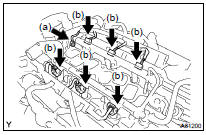
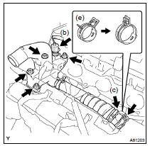
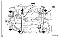
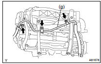
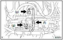
79. REMOVE EMISSION CONTROL VALVE SET
(a) Disconnect the 2 VSV connectors.
(b) Remove the wire harness clamp.
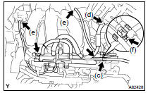
(c) Disconnect the fuel vapor feed hose No. 1.
(d) Disconnect the fuel vapor feed hose No. 2.
(e) Disconnect the 2 vacuum hoses.
(f) Remove the clamp.
(g) Remove the 2 nuts and the emission control valve set.
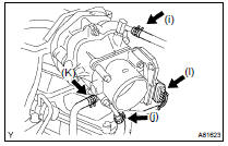
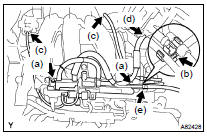
80. REMOVE INTAKE AIR SURGE TANK
(a) Disconnect the throttle motor connector.
(b) Disconnect the water bypass hose No. 3.
(c) Disconnect the water bypass hose No. 2.
(d) Disconnect the union to check valve hose.
(e) Disconnect the ventilation hose.
(f) Remove the 3 nuts and disconnect the pressure feed tube.
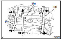
(g) Remove the 2 bolts and engine hanger No. 1.
(h) Remove the 2 bolts and surge tank stay No. 1.
(i) Remove the 2 bolts and surge tank stay No. 2.
(j) Using a socket hexagon wrench 8, remove the 4 bolts.
(k) Remove the 2 nuts, emission control valve bracket and intake air surge tank.
(l) Remove the gasket from the intake air surge tank.
81. INSPECT INTAKE AIR SURGE TANK
(a) Using a precision straight edge and feeler gauge, measure the surface contacting the cylinder head for warpage.
Maximum warpage: 0.10 mm (0.0039 in.)
If the warpage is greater than the maximum, replace the manifold.
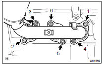
82. REMOVE INTAKE MANIFOLD
(a) Remove the nut and disconnect the ground cable.
(b) Disconnect the 6 fuel injector connectors.
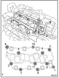
(c) Uniformly loosen and remove the 9 bolts and 2 nuts in the sequence shown in the illustration. Remove the intake manifold.
83. INSPECT INTAKE MANIFOLD
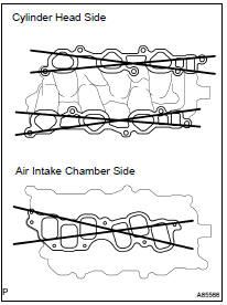
(a) Using a precision straight edge and feeler gauge, measure the surface contacting the cylinder head and intake air surge tank for warpage.
Maximum warpage:
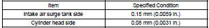
If warpage is greater than the maximum, replace the manifold
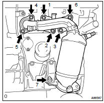
84. REMOVE WATER OUTLET
(a) Disconnect the radiator hose inlet.
(b) Disconnect the engine coolant temperature sensor connector.
(c) Remove the clamp.
(d) Remove the 2 bolts, 2 nuts and 2 washers.
(e) Lock the hose clamp as shown in the illustration and remove the water outlet together with the water bypass hose No. 1.
(f) Remove the 2 gaskets from the 2 cylinder heads.
85. REMOVE IGNITION COIL ASSY
86. REMOVE EXHAUST MANIFOLD CONVERTER SUB-ASSY NO.2
(a) Disconnect the A/F sensor connector.
(b) Remove the bolt, nut and insulator No. 3.
(c) Remove the 2 bolts and insulator No. 2.
(d) Uniformly loosen and remove the 7 nuts in the sequence shown in the illustration.
(e) Remove the converter and gasket.
(f) Remove the 2 bolts and manifold stay.
87. INSPECT EXHAUST MANIFOLD CONVERTER SUB-ASSY NO.2
(a) Using a precision straight edge and feeler gauge, measure the surface contacting the cylinder head for warpage.
Maximum warpage: 0.50 mm (0.0196 in.)
If the warpage is greater than the maximum, replace the manifold.
88. REMOVE ENGINE MOUNTING BRACKET RH
89. REMOVE PUMP BRACKET
(a) Remove the 3 bolts and pump bracket.
90. REMOVE GENERATOR BRACKET NO.1
91. REMOVE COMPRESSOR MOUNTING BRACKET NO.1
92. REMOVE WATER INLET PIPE (See page 16-31 )
93. REMOVE WATER INLET (See page 16-31 )
94. REMOVE THERMOSTAT (See page 16-31 )
95. REMOVE ENGINE OIL PRESSURE SWITCH ASSY
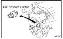
(a) Remove the oil pressure switch.
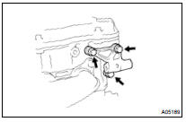
96. REMOVE KNOCK SENSOR
(a) Remove the 2 nuts and 2 sensors.
97. REPLACE PARTIAL ENGINE ASSY
98. INSTALL KNOCK SENSOR
(a) Install the 2 knock sensors with the 2 nuts, as shown in the illustration.
Torque: 20 NVm (204 kgfVcm, 15 ftVlbf)
99. INSTALL ENGINE OIL PRESSURE SWITCH ASSY
(a) Clean the threads of the oil pressure switch. Apply adhesive to 2 or 3 threads of the oil pressure switch.
Adhesive: Part No. 08833-00080 THREE BOND 1344, LOCTITE 242 or equivalent (b) Install the oil pressure switch.
Torque: 15 NVm (153 kgfVcm, 11 ftVlbf)
100. INSTALL THERMOSTAT (See page 16-31 )
101. INSTALL WATER INLET (See page 16-31 )
102. INSTALL WATER INLET PIPE (See page 16-31 )
103. INSTALL COMPRESSOR MOUNTING BRACKET NO.1 Torque: 25 NVm (255 kgfVcm, 18 ftVlbf)
104. INSTALL GENERATOR BRACKET NO.1 Torque: 58 NVm (591 kgfVcm, 43 ftVlbf)
105. INSTALL PUMP BRACKET Torque: 32 NVm (326 kgfVcm, 24 ftVlbf)
106. INSTALL ENGINE MOUNTING BRACKET RH Torque: 54 NVm (551 kgfVcm, 40 ftVlbf)
107. INSTALL EXHAUST MANIFOLD CONVERTER SUB-ASSY NO.2
(a) Install the manifold stay with the 2 bolts, as shown in the illustration.
Torque: 49 NVm (500 kgfVcm, 36 ftVlbf)
(b) Install a new gasket and the converter sub-assy No. 2 with the 7 nuts. Uniformly, tighten the 7 nuts in the sequence shown in the illustration.
Torque: 49 NVm (500 kgfVcm, 36 ftVlbf) (c) Retighten nuts 1 and 2 as shown in the illustration.
(d) Install the insulator No. 2 with the bolt and nut, as shown in the illustration.
Torque: 9.0 NVm (92 kgfVcm, 80 in.Vlbf)
(e) Install the insulator No. 3 with the bolt and nut, as shown in the illustration.
Torque: 9.0 NVm (92 kgfVcm, 80 in.Vlbf) (f) Connect the A/F sensor connector.
108. INSTALL IGNITION COIL ASSY Torque: 8.0 NVm (82 kgfVcm, 71 in.Vlbf)
109. INSTALL WATER OUTLET
(a) Install 2 new gaskets to the 2 cylinder heads.
(b) Install the water outlet together with the water bypass hose No. 1 and unlock the hose clamp.
(c) Tighten the 2 bolts, 2 nuts and 2 washers.
Torque: 15 NVm (153 kgfVcm, 11 ftVlbf) (d) Install the clamp.
(e) Connect the engine coolant temperature sensor connector.
(f) Connect the radiator hose inlet.
110. INSTALL INTAKE MANIFOLD
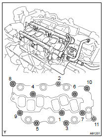
(a) Install the intake manifold with the 9 bolts, 2 nuts and 2 washers. Uniformly tighten the bolts and nuts in the sequence shown in the illustration.
Torque: 15 NVm (153 kgfVcm, 11 ftVlbf) (b) Retighten the water outlet mounting bolts and nuts.
Torque: 15 NVm (153 kgfVcm, 11 ftVlbf) (c) Install the ground cable with the nut.
Torque: 8.0 NVm (82 kgfVcm, 71 in.Vlbf) (d) Connect the heater inlet water hose.
111. INSTALL INTAKE AIR SURGE TANK
(a) Install a new gasket to the intake air surge tank.
(b) Install the intake air surge tank and emission control valve bracket with the 2 nuts.
Torque: 28 NVm (286 kgfVcm, 21 ftVlbf) (c) Using a socket hexagon wrench 8, tighten the 4 bolts.
Torque: 28 NVm (286 kgfVcm, 21 ftVlbf)
(d) Install the surge tank stay No. 2 with the 2 bolts.
Torque: 20 NVm (204 kgfVcm, 15 ftVlbf) (e) Install the surge tank stay No. 1 with the 2 bolts.
Torque: 20 NVm (204 kgfVcm, 15 ftVlbf) (f) Install the engine hanger No. 1 with the 2 bolts.
Torque: 20 NVm (204 kgfVcm, 15 ftVlbf)
(g) Install the pressure feed tube with the 3 nuts.
Torque: 8.0 NVm (82 kgfVcm, 71 in.Vlbf)
(h) Connect the ventilation hose.
(i) Connect the union to the check valve hose.
(j) Connect the water bypass hose No. 2.
(k) Connect the water bypass hose No. 3.
(l) Connect the throttle motor connector.
112. INSTALL EMISSION CONTROL VALVE SET
(a) Install the emission control valve set with the 2 nuts.
Torque: 8.0 NVm (82 kgfVcm, 71 in.Vlbf) (b) Install the clamp.
(c) Connect the 2 vacuum hoses.
(d) Connect the fuel vapor feed hose No. 2.
(e) Connect the fuel vapor feed hose No. 1.
(f) Install the wire harness clamp.
(g) Connect the 2 VSV connectors.
113. INSTALL ENGINE HANGER NO.2 Torque: 20 NVm (204 kgfVcm, 15 ftVlbf)
114. REMOVE ENGINE STAND
115. INSTALL DRIVE PLATE & RING GEAR SUB-ASSY (See page 14-246 )
116. INSTALL ENGINE MOUNTING BRACKET RR
117. INSTALL AUTOMATIC TRANSAXLE W/TRANSFER (4WD TYPE) (See page 40-20 )
118. INSTALL TRANSFER STIFFENER PLATE RH (4WD TYPE)
119. INSTALL AUTOMATIC TRANSAXLE ASSY (2WD TYPE) (See page 40-18 )
120. INSTALL ENGINE MOUNTING BRACKET FR
121. INSTALL STARTER ASSY (See page 19-28 )
122. INSTALL FRONT DRIVE SHAFT ASSY LH (See page 30-21 )
123. INSTALL FRONT DRIVE SHAFT ASSY RH (2WD TYPE) (See page 30-21 )
124. INSTALL FRONT DRIVE SHAFT ASSY RH (4WD TYPE) (See page 30-21 )
125. INSTALL FRONT FRAME ASSY
(a) Install the engine mounting insulator RH and LH with the 2 nuts.
Torque: 95 NVm (969 kgfVcm, 70 ftVlbf)
(b) Install the engine mounting insulator FR with the nut.
Torque: 87 NVm (887 kgfVcm, 64 ftVlbf)
(c) Install the engine mounting insulator RR with the 2 bolts.
Torque: 75 NVm (765 kgfVcm, 55 ftVlbf)
126. INSTALL POWER STEERING LINK ASSY (See page 51-28 )
127. INSTALL STABILIZER BAR FRONT (See page 26-22 )
128. INSTALL VANE PUMP ASSY
(a) Install the vane pump with the 2 bolts.
Torque: 43 NVm (438 kgfVcm, 32 ftVlbf)
HINT: After adjusting the V-ribbed belt, tighten bolt A.
129. INSTALL EXHAUST MANIFOLD CONVERTER SUB-ASSY
(a) Install a new gasket and the exhaust manifold RH. Uniformly tighten the 6 nuts in the sequence shown in the illustration.
Torque: 49 NVm (500 kgfVcm, 36 ftVlbf) (b) Retighten nuts 1 and 2 shown in the illustration.
(c) Install the insulator with the 3 bolts, as shown in the illustration.
Torque: 9.0 NVm (92 kgfVcm, 80 in.Vlbf) (d) Connect the A/F sensor connector.
130. INSTALL ENGINE ASSEMBLY WITH TRANSAXLE
(a) Set the engine assembly with transaxle on the engine lifter.
(b) Install the engine assembly to the vehicle.
(c) Install the frame side rail plate RH and LH with the 6 bolts and 2 nuts.
Torque: 85 NVm (867 kgfVcm, 63 ftVlbf) for bolt A 32 NVm (326 kgfVcm, 24 ftVlbf) for bolt B and nut C
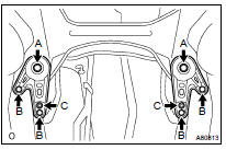
(d) Install the front suspension member brace rear RH and LH with the 6 bolts and 2 nuts.
Torque: 85 NVm (867 kgfVcm, 63 ftVlbf) for bolt A 32 NVm (326 kgfVcm, 24 ftVlbf) for bolt B and nut C
131. CONNECT STEERING INTERMEDIATE SHAFT SUB-ASSY
(a) Align the matchmarks on the intermediate shaft and the control valve shaft, and install the bolt.
Torque: 35 NVm (357 kgfVcm, 26 ftVlbf)
(b) Tighten the sliding yoke bolt.
Torque: 35 NVm (357 kgfVcm, 26 ftVlbf)
132. INSTALL DRIVE PLATE & TORQUE CONVERTER CLUTCH SETTING BOLT
(a) Using SST, hold the crankshaft.
SST 09213-54015 (91651-60855), 09330-00021 (b) Using kerosene or gasoline, clean the bolts thoroughly.
(c) Apply adhesive to 2 or 3 threads of the bolt end.
Adhesive: Part No. 08833-00070, THREE BOND 1324 or equivalent
(d) Install the 6 torque converter set bolts.
Torque: 41 NVm (418 kgfVcm, 30 ftVlbf)
NOTICE: First tighten the green colored bolt and then tighten the 5 bolts.
(e) Install the flywheel housing under cover with the 2 bolts.
Torque: 8.0 NVm (82 kgfVcm, 70 in.Vlbf)
133. INSTALL FRONT SUSPENSION ARM SUB- ASSY LOWER NO.1 LH
(a) Install the drive shaft to the steering knuckle.
(b) Install the suspension lower arm with the bolt and 2 nuts.
Torque: 127 NVm (1,295 kgfVcm, 94 ftVlbf)
134. INSTALL FRONT SUSPENSION ARM SUB-ASSY LOWER NO.1 RH
HINT: Use the same procedures described for the LH side.
135. INSTALL TIE ROD END SUB-ASSY LH
(a) Connect the tie rod end to the steering knuckle and install a new castle nut.
Torque: 49 NVm (500 kgfVcm, 36 ftVlbf)
NOTICE:
- Prevent any lubricant from contacting the thread and the taper portions.
- After tightening the castle nut, tighten it to the additional direction within 60 to put into a cotter pin.
(b) Insert a new cotter pin.
136. INSTALL TIE ROD END SUB-ASSY RH
HINT: Use the same procedures described for the LH side.
137. INSTALL SPEED SENSOR FRONT LH (See page 32-40 )
138. INSTALL SPEED SENSOR FRONT RH (See page 32-40 )
139. INSTALL FRONT AXLE HUB LH NUT
(a) Using a 30 mm socket wrench, install a new hub nut.
Torque: 294 NVm (2,998 kgfVcm, 217 ftVlbf) (b) Using a chisel and hammer, tap the front axle hub LH nut.
140. INSTALL FRONT AXLE HUB RH NUT
HINT: Use the same procedures described for the LH side.
141. INSTALL FRONT STABILIZER LINK ASSY LH
(a) Using a 6 mm socket hexagon wrench, hold the ball stud and install the nut.
Torque: 74 NVm (755 kgfVcm, 55 ftVlbf)
142. INSTALL FRONT STABILIZER LINK ASSY RH
HINT: Use the same procedures described for the LH side.
143. INSTALL EXHAUST PIPE SUPPORT BRACKET NO.1 (See page 15-5 )
144. CONNECT EXHAUST PIPE ASSY FRONT (See page 15-5 )
145. CONNECT EXHAUST PIPE SUB-ASSY FRONT NO.3 (See page 15-5 )
146. INSTALL PROPELLER SHAFT (4WD TYPE) (See page 30-12 )
147. CONNECT ENGINE WIRE
148. INSTALL GLOVE COMPARTMENT DOOR ASSY
149. CONNECT STEERING GEAR OUTLET RETURN TUBE
150. CONNECT OIL RESERVOIR TO PUMP HOSE NO.1
151. CONNECT OIL COOLER OUTLET TUBE NO.1
152. CONNECT OIL COOLER INLET TUBE NO.1
153. CONNECT RADIATOR HOSE OUTLET
154. CONNECT RADIATOR HOSE INLET
155. CONNECT HEATER OUTLET WATER HOSE
156. CONNECT HEATER INLET WATER HOSE
157. CONNECT FUEL PIPE SUB-ASSY NO.1
(a) Push in the fuel tube connector to the fuel pipe until connector makes a "click" sound.
NOTICE:
- Check for damage or contamination on the connected part of the pipe.
- After having finished the connection, check if the pipe and the connector are securely connected by trying to pull them apart.
(b) Install the fuel pipe clamp.
158. CONNECT UNION TO CHECK VALVE HOSE
159. INSTALL TRANSMISSION CONTROL CABLE ASSY (See page 40-20 )
160. INSTALL COMPRESSOR AND MAGNETIC CLUTCH
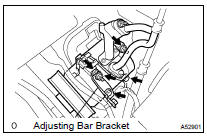
(a) Install the compressor with the 3 bolts.
Torque: 25 NVm (255 kgfVcm, 18 ftVlbf) (b) Install the adjusting bar bracket with the bolt and nut.
Torque: 25 NVm (255 kgfVcm, 18 ftVlbf) for bolt 26 NVm (265 kgfVcm, 19 ftVlbf) for nut
161. INSTALL ENGINE MOUNTING STAY NO.2 RH
(a) Install the mounting stay and mounting bracket with the bolt.
Torque: 64 NVm (653 kgfVcm, 47 ftVlbf)
162. INSTALL ENGINE MOVING CONTROL ROD
(a) Install the control rod and bracket with the 4 bolts.
Torque: 64 NVm (653 kgfVcm, 47 ftVlbf) for bolt A 23 NVm (235 kgfVcm, 17 ftVlbf) for bolt B
163. INSTALL GENERATOR BELT ADJUSTING BAR
(a) Install the adjusting bar with the 2 bolts and 2 nuts.
Torque: 43 NVm (438 kgfVcm, 32 ftVlbf) for nut A 18 NVm (184 kgfVcm, 13 ftVlbf) for bolt B 8.0 NVm (82 kgfVcm, 71 in.Vlbf) for bolt C
164. INSTALL GENERATOR BRACKET NO.2 Torque: 28 NVm (286 kgfVcm, 21 ftVlbf)
165. INSTALL GENERATOR ASSY (See page 19-40 )
166. INSTALL VANE PUMP V BELT (See page 14-125 )
167. INSTALL V (COOLER COMPRESSOR TO CRANKSHAFT PULLEY) BELT NO.1 (See page 14-125 )
168. INSPECT DRIVE BELT TENSION (See page 14-121 )
169. INSTALL AIR CLEANER CASE
170. INSTALL AIR CLEANER FILTER ELEMENT SUB-ASSY
171. INSTALL AIR CLEANER CAP SUB-ASSY
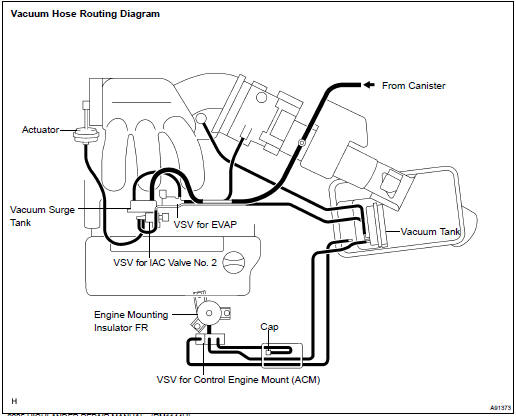
172. CONNECT VACUUM HOSES
173. INSTALL BATTERY
174. INSTALL V-BANK COVER SUB-ASSY
(a) Fit the 2 retainers and install the V-bank cover.
(b) Using a socket hexagon wrench 5, tighten the 3 nuts.
Torque: 8.0 NVm (82 kgfVcm, 71 in.Vlbf)
175. INSTALL FRONT SUSPENSION BRACE SUB-ASSY UPPER CENTER Torque: 80 NVm (816 kgfVcm, 59 ftVlbf)
176. INSTALL COWL PANEL SUB-ASSY
177. INSTALL WINDSHIELD WIPER LINK ASSY (See page 66-7 )
178. INSTALL COWL TOP VENTILATOR LOUVER SUB-ASSY (See page 66-7 )
179. INSTALL FR WIPER ARM LH (See page 66-7 )
180. INSTALL FR WIPER ARM RH (See page 66-7 )
181. INSTALL FRONT WHEELS
182. ADD TRANSFER OIL (4WD TYPE)
183. INSPECT TRANSFER OIL (4WD TYPE)
184. ADD AUTOMATIC TRANSAXLE FLUID
185. ADD ENGINE OIL
186. ADD ENGINE COOLANT (See page 16-26 )
187. ADD POWER STEERING FLUID
188. BLEED POWER STEERING FLUID (See page 51-3 )
189. INSPECT AUTOMATIC TRANSAXLE FLUID
190. CHECK FOR ENGINE OIL LEAKS
191. CHECK FOR ENGINE COOLANT LEAKS (See page 16-20 )
192. CHECK POWER STEERING FLUID LEAKAGE
193. INSPECT FOR FUEL LEAKS
194. CHECK FOR EXHAUST GAS LEAKS
195. INSPECT AND ADJUST FRONT WHEEL ALIGNMENT (See page 26-7 )
196. INSPECT IGNITION TIMING (See page 14-121 )
197. INSPECT ENGINE IDLE SPEED (See page 14-121 )
198. INSPECT CO/HC (See page 14-121 )
199. CHECK ABS SPEED SENSOR SIGNAL (See page 05-765 )
 Components
...
 Overhaul
1. DRAIN ENGINE OIL
2. REMOVE SPARK PLUG
3. REMOVE VENTILATION VALVE SUB-ASSY
4. REMOVE OIL FILLER CAP SUB-ASSY
5. REMOVE OIL FILLER CAP GASKET
6. REMOVE CYLINDER HEAD COVER SUB-ASSY
(a) Rem ...
More about Toyota Highlander:
Terminals of ECU
1. CHECK SLIDING ROOF DRIVE GEAR SUB- ASSY (SLIDING ROOF ECU)
(a) Disconnect the sliding roof ECU connector, and check the
voltage or continuity of each terminal of the wire harness
side connector.
If the result is not as specified, there may be a malfunction on
the wire harness. ...
