Toyota Highlander Service Manual: Inspection
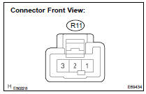
1. HEADLAMP DIMMER SWITCH ASSY
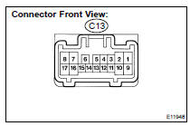
(a) Inspect light control switch.
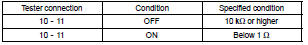
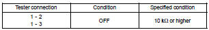
- Measure the resistance according to the value(s) in the table below.
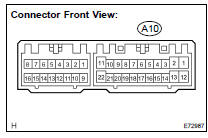
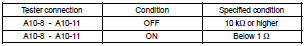
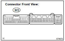
Standard:
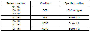
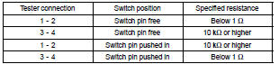
(b) Inspect headlamp dimmer switch.
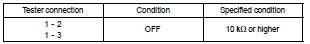
- Measure the resistance according to the value(s) in the table below.
Standard:
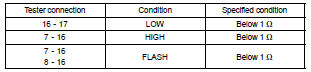
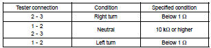
(c) Inspect turn signal switch.
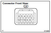
- Measure the resistance according to the value(s) in the table below.
Standard:
(d) w/ Front Fog Lamp: Inspect front fog light switch.
- Measure the resistance according to the value(s) in the table below.
Standard:
2. HAZARD WARNING SWITCH ASSY
(a) w/o navigation system: Measure the resistance according to the value(s) in the table below.
Standard:
(b) w/ navigation system: Measure the resistance according to the value(s) in the table below.
Standard:
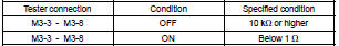
3. FRONT DOOR COURTESY LAMP SWITCH ASSY
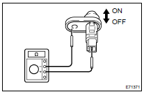
(a) Measure the resistance according to the value(s) in the table below.
Standard:
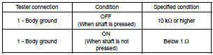
4. REAR DOOR COURTESY LAMP SWITCH ASSY
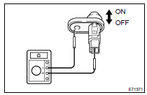
(a) Measure the resistance according to the value(s) in the table below.
Standard:
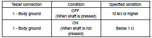
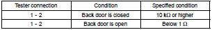
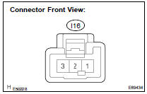
5. BACK DOOR LOCK ASSY
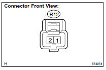
(a) Inspect back door courtesy lamp switch assy.
- Measure the resistance according to the value(s) in the table below.
Standard:
6. ROOM LAMP ASSY NO.1
(a) Measure the resistance according to the value(s) in the table below.
Standard:
b) Connect the positive (+) lead from the battery to the terminal 1 and negative (-) lead to the terminal 2, then check that the lamp comes on when the switch is in the DOOR position.
(c) Connect the positive (+) lead from the battery to the terminal 1 and negative (-) lead to the terminal 3, then check that the lamp comes on when the switch is in the ON position.
7. ROOM LAMP ASSY NO.2
(a) Measure the resistance according to the value(s) in the table below.
Standard:
b) Connect the positive (+) lead from the battery to the terminal 1 and negative (-) lead to the terminal 2, then check that the lamp comes on when the switch is in the DOOR position.
(c) Connect the positive (+) lead from the battery to the terminal 1 and negative (-) lead to the terminal 3, then check that the lamp comes on when the switch is in the ON position.
8. MAP LAMP ASSY
(a) Inspect the map lamp in the overhead J/B.
- Connect the positive (+) lead from the battery to terminal 12 and negative (-) lead to terminal 1, then check that the lamp comes on when the switch is in the ON position.
- Connect the positive (+) lead from the battery to terminal 12 and negative (-) lead to terminal 7, then check that the lamp comes on when the switch is in the DOOR position.
9. COURTESY LAMP ASSY
(a) Connect the positive (+) lead from the battery to terminal 1 and negative (-) lead to terminal 2, then check that the lamp comes on.
10. LH VISOR ASSY
(a) Connect the positive (+) lead from the battery to one of the terminals and the negative (-) lead to other terminal, then check that the lamp comes on when the switch is in the ON position.
11. RH VISOR ASSY
(a) Connect the positive (+) lead from the battery to one of the terminals and the negative (-) lead to other terminal, then check that the lamp comes on when the switch is in the ON position.
12. GLOVE BOX LAMP ASSY
(a) Connect the positive (+) lead from the battery to one of the terminals and the negative (-) lead to other terminal, then check that the lamp comes on when the switch is in the ON position.
13. KEY CYLINDER LAMP
(a) w/ Theft deterrent system: Connect the positive (+) lead from the battery to terminal 2 and negative (-) lead to terminal 6, then check that the lamp comes on.
(b) w/o Theft deterrent system: Connect the positive (+) lead from the battery to terminal 2 and negative (-) lead to terminal 1, then check that the lamp comes on.
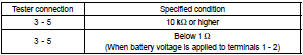
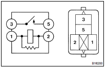
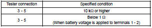
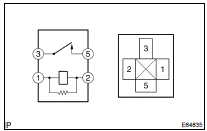
14. HEADLAMP RELAY
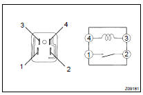
(a) Measure the resistance according to the value(s) in the table below.
Standard:
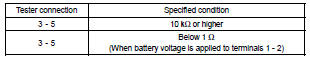
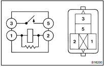
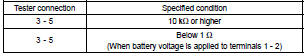
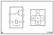
15. TAIL LAMP RELAY
(a) Measure the resistance according to the value(s) in the table below.
Standard:
16. FOG LAMP RELAY
(a) Measure the resistance according to the value(s) in the table below.
Standard:
17. DRL NO.2 RELAY
(a) Measure the resistance according to the value(s) in the table below.
Standard:
18. DRL NO.3 RELAY
(a) Measure the resistance according to the value(s) in the table below.
Standard:
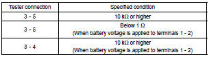
19. DRL NO.4 RELAY
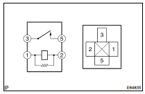
(a) Measure the resistance according to the value(s) in the table below.
Standard:
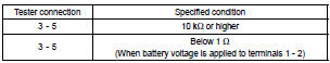
20. STOP LAMP SWITCH ASSY
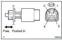
(a) Measure the resistance according to the value(s) in the table below.
Standard:
 On-vehicle inspection
1. INSPECT TURN SIGNAL FLASHER CIRCUIT
(a) Disconnect the connector from the turn signal flasher
relay.
(b) Measure the voltage according to the value(s) in the table
below.
Standard
(c) ...
 LH headlamp ASSY
COMPONENTS
...
More about Toyota Highlander:
Adjustment
1. ADJUST V (COOLER COMPRESSOR TO CRANKSHAFT PULLEY) BELT NO.1
(a) Loosen bolt A.
(b) Loosen bolt B.
(c) Apply drive belt tension by turning bolt C.
Drive belt tension:
New belt: 160 to 180 lbf
Used belt: 115 to 135 lbf
HINT:
"New V belt" refers to a belt which has been used for l ...
