Toyota Highlander Service Manual: Front brake
COMPONENTS
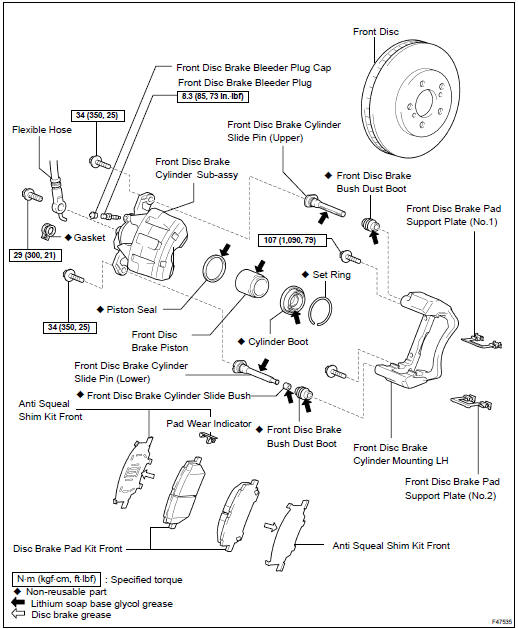
OVERHAUL
HINT:
- Use the same procedures for the RH side and LH side.
- The procedures listed below are for the LH side.
1. REMOVE FRONT WHEEL
2. DRAIN BRAKE FLUID
NOTICE: Wash brake fluid off immediately if it adheres to any painted surface.
3. REMOVE FRONT DISC BRAKE CYLINDER SUB-ASSY
(a) Remove the union bolt and gasket from the disc brake cylinder sub-assy, then disconnect the flexible hose.
(b) Remove the 2 bolts and disc brake cylinder sub-assy.
4. REMOVE DISC BRAKE PAD KIT FRONT (PAD ONLY)
(a) Remove the 2 brake pads with anti-squeal shim.
5. REMOVE ANTI SQUEAL SHIM KIT FRONT
(a) Remove the anti-squeal shim and pad wear indicator plate from inner pad.
(b) Remove the anti-squeal shim from outer pad.
6. REMOVE FRONT DISC BRAKE PAD SUPPORT PLATE
(a) Remove the front disc brake pad support plate (No.1) and front disc brake pad support plate (No.2) from the disk brake cylinder mounting LH.
7. REMOVE FRONT DISC BRAKE CYLINDER SLIDE PIN
(a) Remove the 2 front disc brake cylinder slide pins from the front disc brake cylinder mounting LH.
8. REMOVE FRONT DISC BRAKE CYLINDER SLIDE BUSH
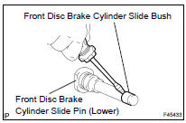
(a) Using a screwdriver, remove the front disc brake cylinder slide bush from the front disc brake cylinder slide pin (lower).
9. REMOVE FRONT DISC BRAKE BUSH DUST BOOT
(a) Remove the 2 front disc brake bush dust boots from the front disc brake cylinder mounting.
10. REMOVE FRONT DISC BRAKE CYLINDER MOUNTING LH
(a) Remove the 2 bolts and front disc brake cylinder mounting LH.
11. REMOVE CYLINDER BOOT
(a) Using a screwdriver, remove the set ring and cylinder boot.
NOTICE: Do not damage the inner cylinder and cylinder groove.
12. REMOVE FRONT DISC BRAKE PISTON
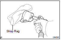
(a) Place a piece of shop rag or equivalent between the front disc brake piston and the front disc brake cylinder subassy.
(b) Use compressed air to remove the front disc brake piston from the front disc brake cylinder sub-assy.
CAUTION: Do not place your fingers in front of the piston when using compressed air.
NOTICE: Do not spatter the brake fluid.
13. REMOVE PISTON SEAL
(a) Using a screwdriver, remove the piston seal from the front disc brake cylinder sub-assy.
NOTICE: Do not damage the inner cylinder and cylinder groove.
14. REMOVE FRONT DISC BRAKE BLEEDER PLUG CAP
(a) Remove the front disc brake bleeder plug cap from the front disc brake bleeder plug.
15. REMOVE FRONT DISC BRAKE BLEEDER PLUG
(a) Remove the front disc brake bleeder plug from the front disc brake cylinder sub-assy.
16. INSPECT BRAKE CYLINDER AND PISTON
(a) Check the cylinder bore and front disc brake piston for rust or scoring.
If necessary, replace the front disc brake cylinder sub-assy and front disc brake piston.
17. INSPECT PAD LINING THICKNESS
(a) Using a ruler, measure the pad lining thickness.
Standard thickness: 12.7 mm (0.500 in.) Minimum thickness: 1.0 mm (0.039 in.)
If the pad lining thickness is equal to the minimum thickness or less, replace the brake pad.
18. INSPECT FRONT DISC BRAKE PAD SUPPORT PLATE
(a) Inspect the front disc brake pad support plate (No.1) and front disc brake pad support plate (No.2).
- Make sure that both have sufficient rebound, have no deformation, cracks or wear, and that all rust and dirt is cleaned off.
If necessary, replace the brake pad support plate.
19. INSPECT DISC THICKNESS
(a) Using a micrometer, measure the disc thickness.
Standard thickness: 28.0 mm (1.102 in.) Minimum thickness: 26.0 mm (1.024 in.)
If the disc thickness is less than the minimum, replace the disc.
20. REMOVE FRONT DISC
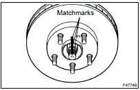
(a) Put matchmarks on the disc and the axle hub.
(b) Remove the disc.
21. INSTALL FRONT DISC
(a) Aligning the matchmarks, install the front disc.
HINT: When replacing the disc with a new one, select the installation position where the front disc has the minimum runout.
22. INSPECT DISC RUNOUT
(a) Temporarily fasten the disc with hub nuts.
Torque: 103 NVm (1,050 kgfVcm, 76 ftVlbf) (b) Using a dial indicator, measure the disc runout 10 mm (0.39 in.) away from the outer edge of the disc.
Maximum disc runout: 0.05 mm (0.0020 in.) (c) If the runout exceeds the maximum value, change the installation positions of the disc and axle so that the runout will become minimal. If the runout exceeds the maximum even when the installation positions are changed, check the bearing play in the axial direction and the axle hub runout (see page 30-3 ). If the bearing play and the axle hub runout are normal and if the disc thickness is not within the specified range, shave the disc. If the disc thickness is less than the minimum, replace the disc.
23. TEMPORARILY TIGHTEN FRONT DISC BRAKE BLEEDER PLUG
(a) Temporarily tighten the front disc brake bleeder plug to the front disc brake cylinder sub-assy.
24. INSTALL FRONT DISC BRAKE BLEEDER PLUG CAP
(a) Install the front disc brake bleeder plug cap to the front disc brake bleeder plug.
25. INSTALL PISTON SEAL
(a) Apply lithium soap base glycol grease to a new piston seal.
(b) Install the piston seal to the front disc brake cylinder sub-assy.
26. INSTALL FRONT DISC BRAKE PISTON
(a) Apply lithium soap base glycol grease to the front disc brake piston.
(b) Install the front disc brake piston to the front disc brake cylinder sub-assy smoothly.
NOTICE: Do not install the front disc brake piston forcibly in the front disc brake cylinder sub-assy.
27. INSTALL CYLINDER BOOT
(a) Apply lithium soap base glycol grease to a new cylinder boot. Install the cylinder boot to the front disc brake cylinder sub-assy.
HINT: Install the boot securely to the grooves of the cylinder and piston.
(b) Using a screwdriver, install a new set ring.
NOTICE:
- Install the boot securely to the grooves of the cylinder and piston.
- Do not damage the cylinder boot.
28. INSTALL FRONT DISC BRAKE CYLINDER MOUNTING LH
(a) Install the front disc brake cylinder mounting LH with the 2 bolts.
Torque: 107 NVm (1,090 kgfVcm, 79 ftVlbf)
29. INSTALL FRONT DISC BRAKE BUSH DUST BOOT
(a) Apply lithium soap base glycol grease to seal surface of 2 new front disc brake bush dust boots.
(b) Install the 2 front disc brake bush dust boots to the front disc brake cylinder mounting LH.
30. INSTALL FRONT DISC BRAKE CYLINDER SLIDE BUSH
(a) Apply lithium soap base glycol grease to a new front disc brake cylinder slide bush.
(b) Install the front disc brake cylinder slide bush to the front disc brake cylinder slide pin (lower).
31. INSTALL FRONT DISC BRAKE CYLINDER SLIDE PIN
(a) Apply lithium soap base glycol grease to the sliding part and the seal surface of the 2 front disc brake cylinder slide pins.
(b) Install the 2 front disc brake cylinder slide pins to the front disc brake cylinder mounting LH.
NOTICE: Insert the slide pin with slide bush into the lower side.
32. INSTALL FRONT DISC BRAKE PAD SUPPORT PLATE
(a) Install the front disc brake pad support plate (No.1) and front disc brake pad support plate (No.2) to the front disc brake cylinder mounting LH.
33. INSTALL ANTI SQUEAL SHIM KIT FRONT
NOTICE:
- If necessary, replace the anti squeal shim kit when replacing the brake pad.
- Install the shims in the correct position and direction.
(a) Apply disc brake grease to inside of each anti-squeal shim.
(b) Install anti-squeal shims on each pad.
(c) Install the pad wear indicator plate to the inner pad.
34. INSTALL DISC BRAKE PAD KIT FRONT (PAD ONLY)
(a) Install the inner pad with the pad wear indicator plate facing upward, and install the outer pad.
NOTICE: There should be no oil or grease on the friction surface of the pads and the disc.
35. INSTALL FRONT DISC BRAKE CYLINDER SUB-ASSY
(a) Install the front disc brake cylinder sub-assy with the 2 bolts.
Torque: 34 NVm (350 kgfVcm, 25 ftVlbf) (b) Install a new gasket and flexible hose with the union bolt.
Torque: 29 NVm (300 kgfVcm, 21 ftVlbf)
NOTICE: Install the flexible hose lock securely in the lock hole in the disc brake cylinder.
36. FILL RESERVOIR WITH BRAKE FLUID (SEE PAGE 32-4 )
37. BLEED MASTER CYLINDER (SEE PAGE 32-4 )
SST 09023-00101
38. BLEED BRAKE LINE (SEE PAGE 32-4 )
39. BLEED BRAKE ACTUATOR ASSY (SEE PAGE 32-4 )
40. CHECK BRAKE FLUID LEAKAGE
41. CHECK FLUID LEVEL IN RESERVOIR (SEE PAGE 32-4 )
42. INSTALL FRONT WHEEL
Torque: 103 NVm (1,050 kgfVcm, 76 ftVlbf)
 Replacement
1. REMOVE FRONT SUSPENSION BRACE SUB-ASSY UPPER CENTER (SEE PAGE 32-14 )
2. REMOVE AIR CLEANER ASSY (2AZ-FE ENGINE TYPE) (SEE PAGE 14-24 )
3. REMOVE AIR CLEANER CAP SUB-ASSY (3MZ-FE ENGINE TYPE) (SE ...
 Rear brake
COMPONENTS
OVERHAUL
HINT:
Use the same procedures for the RH side and LH side.
The procedures listed below are for the LH side.
1. REMOVE REAR WHEEL
2. DRAIN BRAKE FLUID
NOTICE:
Wash b ...
More about Toyota Highlander:
Turn signal lever
Operating instructions
Right turn
Lane change to the right (move
the lever partway and release
it)
the right hand signals will flash 3
times.
Lane change to the left (move
the lever partway and release
it)
the left hand signals will flash 3
times.
Left turn
Turn sign ...
