Toyota Highlander Service Manual: Replacement
1. DISCHARGE FUEL SYSTEM PRESSURE (See page 11-35 )
2. DRAIN ENGINE COOLANT (See page 16-26 )
3. REMOVE FRONT SUSPENSION BRACE SUB-ASSY UPPER CENTER (w/ Performance Rod)
(a) Remove the 2 nuts and upper brace.
4. REMOVE V-BANK COVER SUB-ASSY (See page 14-149 )
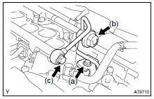
5. REMOVE AIR CLEANER CAP SUB-ASSY
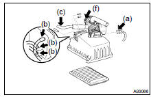
(a) Disconnect the MAF meter connector.
(b) Disconnect the 3 vacuum hoses.
(c) Disconnect the ventilation hose No. 2.
(d) Loosen the air cleaner hose clamp bolt, and remove the air cleaner cap.
(e) Remove the air cleaner filter element.
6. REMOVE EMISSION CONTROL VALVE SET
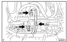
(a) Disconnect the 2 VSV connectors.
(b) Remove the wire harness clamp.
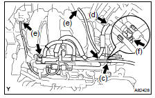
(c) Disconnect the fuel vapor feed hose No. 1.
(d) Disconnect the fuel vapor feed hose No. 2.
(e) Disconnect the 2 vacuum hoses.
(f) Remove the clamp.
(g) Remove the 2 nuts and the emission control valve set.
7. REMOVE INTAKE AIR SURGE TANK
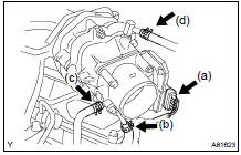
(a) Disconnect the throttle motor connector.
(b) Disconnect the water by-pass hose No. 3.
(c) Disconnect the water by-pass hose No. 2.
(d) Disconnect the union to check valve hose.
(e) Disconnect the ventilation hose.
(f) Remove the 3 nuts and separate the pressure feed tube.
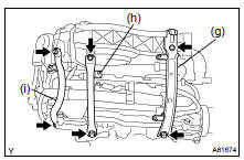
(g) Remove the 2 bolts and engine hanger No. 1.
(h) Remove the 2 bolts and surge tank stay No. 1.
(i) Remove the 2 bolts and surge tank stay No. 2.
(j) Using a socket hexagon wrench 8, remove the 4 bolts.
(k) Remove the 2 nuts, emission control valve bracket and intake air surge tank.
(l) Remove the gasket from the intake air surge tank.
8. SEPARATE FUEL PIPE SUB-ASSY NO.1
(a) Remove the bolt and disconnect the fuel pipe No. 1.
(b) Remove the fuel pressure pulsation damper and 2 gaskets.
(c) Remove the fuel pipe No. 2 union bolt and 2 gaskets.
9. REMOVE FUEL INJECTOR ASSY
(a) Disconnect the 6 fuel injector connectors.
(b) Remove the 4 bolts and 2 fuel delivery pipes together with the 6 fuel injectors.
NOTICE: Be careful not to drop the fuel injectors when removing the fuel delivery pipe.
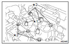
(c) Remove the 4 delivery pipe No. 1 spacers ( 1) and 6 insulators ( 2) from the intake manifold.
(d) Pull out the fuel injector from the fuel delivery pipe.
10. INSTALL FUEL INJECTOR ASSY
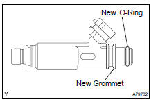
(a) Install a new grommet to each injector.
(b) Apply a light coat of grease or gasoline to a new O-ring, and install it to each injector.
(c) Apply a light coat of grease or gasoline on the place where the fuel delivery pipe contacts the O-ring.
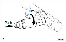
(d) Push the fuel injector while twisting it back and forth to install it in the fuel delivery pipe.
NOTICE: Be careful not to twist the O-ring.
After installing the fuel injector, check that it turns smoothly. If not, reinstall it with a new O-ring.
(e) Install 6 new insulators and the 4 delivery pipe No. 1 spacers to the intake manifold.
(f) Place the 2 fuel delivery pipes and 6 fuel injectors together on the intake manifold.
NOTICE: Be careful not to drop the fuel injectors when installing the fuel delivery pipe.
(g) Temporarily install the 4 bolts which are used to attach the fuel delivery pipe to the intake manifold.
NOTICE: After installing the fuel injector, check that it turns smoothly.
If not, reinstall it with a new O-ring.
(h) Tighten the 4 bolts.
Torque: 10 NVm (102 kgfVcm, 7 ftVlbf) (i) Connect the 6 fuel injector connectors.
11. INSTALL FUEL PIPE SUB-ASSY NO.1
(a) Install 2 new gaskets and the fuel pipe No. 2 union bolt.
Torque: 33 NVm (337 kgfVcm, 24 ftVlbf) (b) Install 2 new gaskets and the fuel pressure pulsation damper.
Torque: 33 NVm (337 kgfVcm, 24 ftVlbf) (c) Install the fuel pipe No. 1 with the bolt.
Torque: 20 NVm (204 kgfVcm, 15 ftVlbf)
12. INSTALL INTAKE AIR SURGE TANK
(a) Install a new gasket to the intake air surge tank.
(b) Install the intake air surge tank and emission control valve bracket with the 2 nuts.
Torque: 28 NVm (286 kgfVcm, 21 ftVlbf) (c) Using a socket hexagon wrench 8, tighten the 4 bolts.
Torque: 28 NVm (286 kgfVcm, 21 ftVlbf) (d) Install the surge tank stay No. 2 with the 2 bolts.
Torque: 20 NVm (204 kgfVcm, 15 ftVlbf) (e) Install the surge tank stay No. 1 with the 2 bolts.
Torque: 20 NVm (204 kgfVcm, 15 ftVlbf) (f) Install the engine hanger No. 1 with the 2 bolts.
Torque: 20 NVm (204 kgfVcm, 15 ftVlbf) (g) Install the pressure feed tube with the 3 nuts.
Torque: 7.8 NVm (80 kgfVcm, 69 in.Vlbf) (h) Connect the ventilation hose.
(i) Connect the union to check valve hose.
(j) Connect the water bypass hose No. 2.
(k) Connect the water bypass hose No. 3.
(l) Connect the throttle motor connector.
13. INSTALL EMISSION CONTROL VALVE SET Torque: 8.0 NVm (82 kgfVcm, 71 in.Vlbf)
14. INSTALL AIR CLEANER CAP SUB-ASSY
15. CHECK CONNECTION OF VACUUM HOSE (See page 14-149 )
16. ADD ENGINE COOLANT (See page 16-26 )
17. CHECK FOR ENGINE COOLANT LEAKS (See page 16-20 )
18. CHECK FOR FUEL LEAKS (See page 11-38 )
19. INSTALL V-BANK COVER SUB-ASSY (See page 14-149 )
20. INSTALL FRONT SUSPENSION BRACE SUB-ASSY UPPER CENTER (w/ Performance Rod)
(a) Install the upper brace with the 2 nuts.
Torque: 80 NVm (815 kgfVcm, 59 ftVlbf)
 Components
...

More about Toyota Highlander:
Washer fluid
If any washer does not work or the
warning message appears on the
multi-information display, the
washer tank may be empty. Add
washer fluid.
Warning
When adding washer fluid
Do not add washer fluid when the engine is hot or running as washer
fluid
contains alcohol and ma ...
