Toyota Highlander Service Manual: Front seat ASSY LH (manual seat type
COMPONENTS
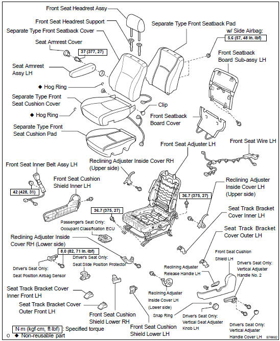
OVERHAUL
CAUTION:
- Wear safety gloves, because the cutting surface of the seatback frame and seat adjuster may injure your hand.
- Work must be at least 90 seconds after the ignition switch is turned
to the LOCK position and
the negative (-) terminal cable is disconnected from the battery.
(The SRS is equipped with a back-up power source. If work is started within 90 seconds from disconnecting the negative (-) terminal cable of the battery, the SRS may deploy.)
HINT:
- The installation procedures are the removal procedures in reverse order. However, only installation procedures requiring additional information are included.
- Use the same procedures for the RH side and LH side.
- The procedures listed below are for the LH side.
- When removing/installing and overhauling the passenger seat, check the passenger occupant classification system and perform the zero point calibration (see page 05-1203 ).
- A bolt without a torque specification is shown in the standard bolt chart (see page 03-2 ).
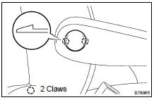
1. REMOVE SEAT TRACK BRACKET COVER OUTER FRONT LH
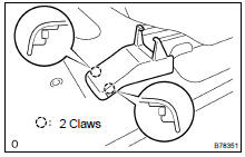
(a) Using a screwdriver, disengage 2 claws and remove the bracket cover.
HINT: Tape the screwdriver tip before use.
2. REMOVE SEAT TRACK BRACKET COVER INNER FRONT LH
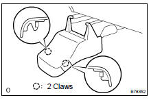
(a) Using a screwdriver, disengage the 2 claws and remove the bracket cover.
HINT: Tape the screwdriver tip before use.
3. REMOVE SEAT TRACK BRACKET COVER OUTER LH
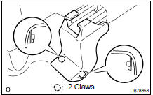
(a) Using a screwdriver, disengage the 2 claws and remove the bracket cover.
HINT: Tape the screwdriver tip before use.
4. REMOVE SEAT TRACK BRACKET COVER INNER LH
HINT: Use the same procedures described for the bracket cover outer LH.
Tape the screwdriver tip before use.
5. REMOVE FRONT SEAT ASSY LH
(a) Remove the headrest.
(b) Disconnect the connectors under the seat.
(c) Remove the 4 bolts and seat.
NOTICE: Be careful not to damage the body.
6. Passenger's seat only: REMOVE OCCUPANT CLASSIFICATION ECU (See page 60-64 )
7. Driver's seat only: REMOVE VERTICAL SEAT ADJUSTER KNOB LH
(a) Using a cloth, remove the snap rings and vertical seat adjuster knob.
8. Driver's seat only: REMOVE VERTICAL ADJUSTING HANDLE NO.2
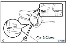
(a) Using a screwdriver, disengage the 3 claws and remove the vertical adjuster handle cover LH.
HINT: Tape the screwdriver tip before use.
(b) Remove the 2 screws and vertical adjusting handle.
9. REMOVE RECLINING ADJUSTER RELEASE HANDLE LH
(a) Using a screwdriver, pry out the reclining adjuster release handle.
HINT: Tape the screwdriver tip before use.
10. REMOVE FRONT SEAT CUSHION SHIELD LH
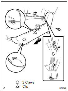
(a) Remove the 2 rubber bands from the back of the seatback board cover.
(b) Remove the screw.
(c) Using a screwdriver, disengage the 2 claws and clip, and remove the cushion shield.
HINT: Tape the screwdriver tip before use.
11. REMOVE FRONT SEAT CUSHION SHIELD INNER LH
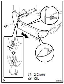
(a) Remove the screw.
(b) Using a screwdriver, disengage the 2 claws and clip, and remove the cushion shield.
HINT: Tape the screwdriver tip before use.
12. REMOVE FRONT SEAT INNER BELT ASSY LH (See page 61-4 )
13. REMOVE SEPARATE TYPE FRONT SEAT CUSHION COVER
(a) Remove the 2 clips on the cushion cover side.
(b) w/ Seat heater: Disconnect the seat heater connectors..
(c) Disengage the hook and remove the hog rings and seat cushion cover together with the pad..
(d) Remove the hog rings and cushion cover
14. REMOVE FRONT SEATBACK BOARD SUB-ASSY LH
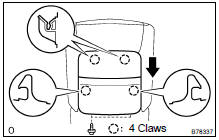
(a) Remove the 2 screws.
(b) Lower the seatback board in the direction indicated by the arrow in the illustration to disengage the 4 claws on the upper part.
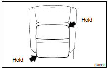
(c) Hold the seatback board on the upper right and lower left as shown in the illustration.
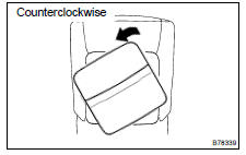
(d) Turn the seatback board counterclockwise to disengage the claws and remove it.
15. REMOVE FRONT SEATBACK BOARD COVER SUB-ASSY
(a) Disengage the hook on the upper part of the seatback board cover.
(b) Remove the hog rings and seatback board cover.
16. REMOVE SEAT ARMREST ASSY LH
(a) Using a screwdriver, disengage the 2 claws and remove the armrest cover.
HINT: Tape the screwdriver tip before use.
(b) Remove the bolt and armrest.
17. REMOVE SEPARATE TYPE FRONT SEATBACK COVER
(a) Remove the 2 headrest supports.
(b) Remove the hog rings and seatback cover together with the pad.
(c) w/ Side airbag: Remove the nut and seatback cover bracket.
(d) Remove the hog rings and seatback cover.
18. REMOVE RECLINING ADJUSTER INSIDE COVER LH (UPPER SIDE)
(a) Remove the screw and cushion shield.
19. REMOVE RECLINING ADJUSTER INSIDE COVER RH (UPPER SIDE)
(a) Remove the screw and cushion shield.
20. REMOVE RECLINING ADJUSTER INSIDE COVER LH (LOWER SIDE)
(a) Remove the screw and cushion shield.
21. REMOVE RECLINING ADJUSTER INSIDE COVER RH (LOWER SIDE)
(a) Remove the screw and cushion shield.
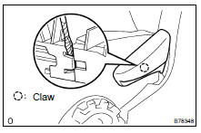
22. REMOVE FRONT SEAT CUSHION SHIELD LOWER LH
(a) Disengage the claw and remove the cushion shield.
23. REMOVE FRONT SEAT CUSHION SHIELD LOWER RH
(a) Disengage the claw and remove the cushion shield.
24. Driver's seat only: REMOVE SEAT POSITION AIRBAG SENSOR
(a) Disconnect the wire harness connector.
(b) Disengage the claw and remove the seat slide position protector.
(c) Using a torx) socket wrench (T30), remove the torx) bolt and airbag sensor.
25. INSTALL SEAT POSITION AIRBAG SENSOR
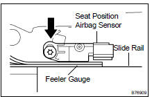
(a) Temporarily install the seat position airbag sensor.
(b) Install a 1 mm (0.04 in.) feeler gauge between the slide rail and sensor as shown in the illustration.
NOTICE:
- If the seat position airbag sensor has been dropped, or there are any cracks, dents or other defects in the case, bracket or connector, replace the seat position airbag sensor with a new one.
- When installing the seat position airbag sensor, be careful that the SRS wiring does not interfere with other parts and is not pinched between other parts.
HINT: Be sure to that a clearance between the seat position airbag sensor and the seat rail is within 0.6 mm (0.023 in.) to 2 mm (0.079 in.).
(c) Push the top of the sensor. While holding the sensor, tighten the sensor using a torx) socket wrench (T30).
Torque: 8.0 NVm (82 kgfVcm, 71 in.Vlbf)
(d) Install the seat slide position protector
26. INSTALL SEPARATE TYPE FRONT SEATBACK COVER
(a) Install the seatback pad.
(b) Cover the top of the seatback pad with the seatback cover.
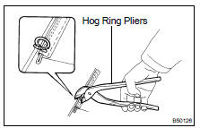
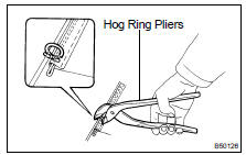
(c) Using hog ring pliers, completely install the seatback cover with new hog rings.
NOTICE:
- Be careful not to damage the cover.
- When installing the hog rings, take care to prevent wrinkles as much as possible.
(d) Install the 2 headrest supports.
(e) w/ Side airbag: Fully cover the airbag with the seatback cover bracket and tighten the nut.
Torque: 5.6 NVm (57 kgfVcm, 49 in.Vlbf)
NOTICE:
- For a vehicle with side airbag, the side airbag may not be activated normally unless the seatback cover is securely installed.
- Check that the strap has no twist after installing the bracket.
- Install the bracket securely.
27. INSTALL SEAT ARMREST ASSY LH
(a) Install the armrest with the bolt.
Torque: 37 NVm (377 kgfVcm, 27 ftVlbf)
(b) Install the armrest cover.
28. INSTALL SEPARATE TYPE FRONT SEAT CUSHION COVER
(a) Install the seat cushion.
(b) Using hog ring pliers, install the cushion cover to the cushion pad with new hog rings.
NOTICE:
- Be careful not to damage the cover.
- When installing the hog rings, take care to prevent wrinkles as much as possible.
(c) w/ Seat heater: Connect the seat heater connectors.
(d) Install the clip.
29. INSTALL FRONT SEAT INNER BELT ASSY LH (See page 61-4 )
30. INSTALL FRONT SEAT ASSY LH
(a) Place the seat in the cabin.
(b) Connect the connectors under the seat.
(c) Tighten the 2 bolts on the front side of the seat.
Torque: 36.7 NVm (375 kgfVcm, 27 ftVlbf)
(d) Tighten the 2 bolts on the rear side of the seat.
Torque: 36.7 NVm (375 kgfVcm, 27 ftVlbf)
(e) Install the 4 seat track covers.
(f) Install the headrest.
(g) Connect the battery's negative terminal.
31. w/ Seat heater: CHECK SEAT HEATER OPERATION
32. Passenger's seat only: CHECK FUNCTION OF FRONT PASSENGER OCCUPANT CLASSIFICATION SYSTEM
HINT:
- Perform the zero point calibration and sensitivity check when any of the following conditions is met.
- The occupant classification ECU is replaced.
- Accessories (seatback tray and seat cover, etc.) are installed.
- The passenger seat is removed from the vehicle.
- Both the SRS warning lamp and the passenger airbag ON/OFF indicator lamp ("OFF") turn on.
- The vehicle is brought to the workshop for repair due to an accident or a collision.
(a) Zero point calibration procedure:
- Adjust the seat position according to the table below.
|
Adjustment Component |
Position |
| Slide Direction | Rearmost position |
| Reclining Angle | Upright position |
| Headrest Height | Lowest position |
- Connect the hand-held tester to the DLC3.
- Turn the ignition switch ON.
- Perform the zero point calibration by following the prompts on the tester screen.
HINT: Refer to the hand-held tester operator's manual for further details.
(b) Sensitivity check procedure:
- Connect the hand-held tester to the DLC3.
- Apply a 30 kg weight (for example, a 30 kg of lead mass) onto the passenger seat.
- Turn the ignition switch ON.
- Using the hand-held tester, perform the sensitivity check and confirm that the sensitivity is within the standard value.
Standard value: 27 to 33 kg
HINT:
- When performing the sensitivity check, use a solid weight made from metal. The check results may not be accurate if a weight made from liquid is used.
- When the sensitivity deviates from the standard value, retighten the bolts of the passenger seat, taking care not to deform the seat rail. Perform the sensitivity check again. If the sensitivity still is not within the standard value, replace the front seat assembly RH.
NOTICE: Do not place any objects on the seat. Perform the initialization by attaching a mass more than 2 kgs in the seatback pocket, seatback table installed by the user, or other appropriate location.
(c) Check the SRS warning lamp (see page 60-1 ).
 Front seat ASSY LH (power seat type)
COMPONENTS
OVERHAUL
CAUTION:
Wear safety gloves, because the cutting surfaces of the seatback
frame and seat adjuster may
injure your hand.
Work must be started at least 90 seconds afte ...
 Rear NO.1 seat ASSY LH (W/O rear NO.2 seat)
COMPONENTS
OVERHAUL
HINT:
The installation procedures are the removal procedures in reverse
order. However, only installation
procedures requiring additional information are included.
...
More about Toyota Highlander:
Cleaning and protecting
the vehicle interior
The following procedures will help protect your vehicle’s interior
and keep it in top condition:
Protecting the vehicle interior
Remove dirt and dust using a vacuum cleaner. Wipe dirty surfaces
with a cloth dampened with lukewarm water.
Cleaning the leather areas
Remove dirt and dust usin ...
