Toyota Highlander Service Manual: Cooler compressor ASSY (2AZ-FE)
COMPONENTS
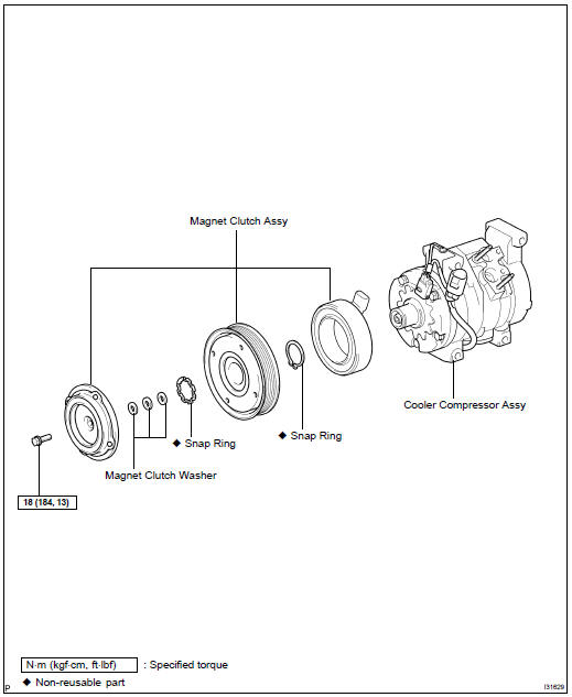
REPLACEMENT
HINT: COMPONENTS: see page 55-44
1. DISCHARGE REFRIGERANT FROM REFRIGERATION SYSTEM (SEE PAGE 55-17 )
2. REMOVE V (COOLER COMPRESSOR TO CRANKSHAFT PULLEY) BELT NO.1 (SEE PAGE 14-5 )
3. REMOVE GENERATOR ASSY (SEE PAGE 19-16 )
4. DISCONNECT COOLER REFRIGERANT DISCHARGE HOSE NO.1
(a) Remove the nut and disconnect the cooler refrigerant discharge hose No.1.
(b) Remove the O-ring from the cooler refrigerant discharge hose No.1.
NOTICE: Seal the opening of the disconnected parts using vinyl tape to prevent moisture and foreign matter from entering.
5. DISCONNECT COOLER REFRIGERANT SUCTION HOSE NO.1
(a) Remove the nut and disconnect the cooler refrigerant suction hose No.1.
(b) Remove the O-ring from the cooler refrigerant suction hose No.1.
NOTICE: Seal the opening of the disconnected parts using vinyl tape to prevent moisture and foreign matter from entering.
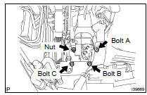
6. REMOVE COMPRESSOR AND MAGNETIC CLUTCH
(a) Disconnect the connector.
(b) Remove the nut.
(c) Using a E8 torque socket wrench, remove the stud bolt.
(d) Remove the 3 bolts and compressor and magnetic clutch.
7. REMOVE MAGNET CLUTCH ASSY
(a) Remove the bolt and the bracket.
(b) Place the compressor and magnetic clutch in a vise.
NOTICE: Do not get the bracket and harness caught in the vise.
(c) Using SST, hold the magnet clutch hub.
SST 95047-10400
(d) Remove the bolt, magnet clutch hub and magnet clutch washer.
HINT: There is no set number of magnet clutch washers since they are used for adjusting.
(e) Using a snap ring expander, remove the snap ring and magnet clutch rotor.
NOTICE: Do not damage the seal cover of the bearing when removing the snap ring.
(f) Remove the screw and disconnect the connector.
(g) Using a snap ring expander, remove the snap ring and magnet clutch stator.
8. INSTALL MAGNET CLUTCH ASSY
(a) Fit the parts as shown in the illustration and install the magnet clutch stator.
(b) Using a snap ring expander, install a new snap ring with the chamfered side facing up.
NOTICE: Do not damage the seal cover of the bearing when removing the snap ring.
(c) Install the screw and connect the connector.
(d) Using a snap ring expander, install the magnet clutch rotor and a new snap ring with the chamfered side facing up.
NOTICE:
- Do not expand the snap ring by more than 30.5 mm (1.2 in) when installing it.
- Do not damage the seal cover of the bearing when removing the snap ring.
(e) Install the magnet clutch washer and magnet clutch hub.
NOTICE: Do not change the combination of the magnet clutch washers used before disassembly.
(f) Using SST, hold the magnet clutch hub and install the bolt.
SST 95047-10400
Torque: 18 NVm (183 kgfVcm, 13 ftVlbf)
NOTICE: Make sure that there is no foreign matter or oil on the compressor shaft, bolt, and clutch hub.
9. INSPECT MAGNETIC CLUTCH CLEARANCE
(a) Set the dial gage to the magnet clutch hub.
(b) Connect the positive battery lead to terminal 3 of the magnet clutch connector and the negative lead to the earth wire. Turn on and off the magnet clutch and measure the clearance.
Standard clearance: 0.35 to 0.60 mm (0.013 to 0.023 in.)
If the measured value is not within the standard range, remove the magnet clutch hub and adjust it with magnet clutch washers.
NOTICE: Adjustment shall be performed with 3 or less magnet clutch washers.
(c) Remove the compressor and magnetic clutch from the vise.
(d) Install bracket with the bolt.
10. INSPECT COMPRESSOR OIL
(a) When replacing the compressor and magnetic clutch with new one, after gradually removing the refrigerant gas from the service valve, drain the following amount of oil from the new compressor and magnetic clutch before installation.
Standard: (Oil capacity inside new cooler compressor assy: 120 + 15 cc (4.06 + 0.5 fl.oz.)) - (Remaining oil amount in the removed cooler compressor assy) = (Oil amount to be removed when replacing)
NOTICE:
- When checking the compressor oil level, observe the precautions on the cooler removal/installation.
- Because compressor oil remains in the pipes of the vehicle, if a new cooler compressor assy is installed without removing some oil inside, the oil amount becomes too much, preventing heat exchange in the refrigerant cycle and causing refrigerant failure.
- If the remaining oil in the removed cooler compressor assy is too small in volume, check for oil leakage.
- Be sure to use ND-OIL8 for compressor oil.
11. TEMPORARILY TIGHTEN COMPRESSOR AND MAGNETIC CLUTCH
(a) Install the compressor and magnetic clutch with the stud bolt, 3 bolts and nut.
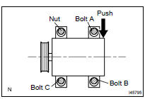
12. FULLY TIGHTEN COMPRESSOR AND MAGNETIC CLUTCH
(a) Temporarily tighten nut.
HINT: Do not over tighten the bolt until the compressor no longer moves.
(b) Push down on the rear side of the compressor and fully tighten bolt B, bolt C, bolt A and nut in order.
(c) Connect the connector.
13. INSTALL COOLER REFRIGERANT SUCTION HOSE NO.1
(a) Remove the attached vinyl tape from the hose.
(b) Sufficiently apply compressor oil to the O-ring and fit surface of the compressor and magnetic clutch.
(c) Install a new O-ring to the cooler refrigerant suction hose No.1.
Compressor oil: ND-OIL 8 or equivalent
(d) Install the cooler refrigerant suction hose No.1 to the compressor and magnetic clutch with the nut.
Torque: 9.8 NVm (100 kgfVcm, 87 in.Vlbf)
14. INSTALL COOLER REFRIGERANT DISCHARGE HOSE NO.1
(a) Remove the attached vinyl tape from the hose.
(b) Sufficiently apply compressor oil to the O-ring and fit surface of the compressor and magnetic clutch..
(c) Install a new O-ring to the cooler refrigerant discharge hose No.1.
Compressor oil: ND-OIL 8 or equivalent
(d) Install the cooler refrigerant discharge hose No.1 to the compressor and magnetic clutch with the nut.
Torque: 9.8 NVm (100 kgfVcm, 87 in.Vlbf)
15. INSTALL BELT, V-RIBBED (SEE PAGE 14-5 ) 16. INSTALL GENERATOR ASSY (SEE PAGE 19-16 ) 17. CHARGE REFRIGERANT (SEE PAGE 55-17 ) 18. WARM UP ENGINE (SEE PAGE 55-17 ) 19. INSPECT LEAKAGE OF REFRIGERANT (SEE PAGE 55-17 )
 Blower ASSY
COMPONENTS
OVERHAUL
HINT:
COMPONENTS: see page 55-40
1. REMOVE GLOVE COMPARTMENT DOOR ASSY(SEE PAGE 71-10 )
2. REMOVE AIR DUCT NO.2
(a) Remove the screw.
(b) Release the 3 claw fittings a ...
 Cooler compressor ASSY (3MZ-FE)
COMPONENTS
REPLACEMENT
HINT:
COMPONENTS: see page 55-51
1. DISCHARGE REFRIGERANT FROM REFRIGERATION SYSTEM (SEE PAGE 55-17 )
SST 07110-58060 (07117-58080, 07117-58090, 07117-78050, 07117-88060, ...
More about Toyota Highlander:
List of storage features
Auxiliary boxes
Open tray
Glove box
Bottle holders
Cup holders
Console box
Warning
Do not leave glasses, lighters or spray cans in the storage
spaces, as this
may cause the following when cabin temperature becomes high:
Glasses may be def ...
