Toyota Highlander Service Manual: Camshaft (2AZ-FE)
REPLACEMENT
1. REMOVE FRONT WHEEL RH
2. REMOVE FRONT FENDER SPLASH SHIELD FRONT RH
3. REMOVE FRONT FENDER APRON SEAL RH
4. REMOVE ENGINE COVER SUB-ASSY NO.1
5. REMOVE IGNITION COIL ASSY
6. REMOVE SPARK PLUG
7. DISCONNECT VENTILATION HOSE
8. DISCONNECT VENTILATION HOSE NO.2
9. DISCONNECT ENGINE WIRE
10. REMOVE CYLINDER HEAD COVER SUB-ASSY (See page 14-41 )
11. SET NO. 1 CYLINDER TO TDC/COMPRESSION (See page 14-6 )
12. REMOVE CHAIN TENSIONER ASSY NO.1 (See page 14-41 )
13. REMOVE NO.2 CAMSHAFT (EXHAUST)
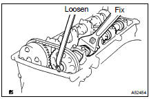
(a) Fix the camshaft with a wrench, and then loosen the sprocket bolt.
NOTICE: Be careful not to damage the valve lifter.
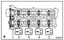
(b) Loosen and remove the bearing cap bolts on No. 2 camshaft (exhaust) in the sequence shown in the illustration in several passes, and remove the 5 bearing caps.
(c) Raise the No. 2 camshaft (exhaust) and remove it. Then remove the sprocket bolt.
(d) Disconnect the camshaft timing sprocket (with the timing chain) from the No. 2 camshaft (exhaust).
(e) Remove the camshaft timing sprocket from the timing chain.
14. REMOVE CAMSHAFT (INTAKE)
(a) Loosen the bearing cap bolts on camshaft (intake) in the sequence shown in the illustration in several passes, and remove the caps.
(b) Remove the camshaft
(c) Tie the timing chain with a string.
NOTICE: Do not drop anything inside the timing chain cover.
15. REMOVE CAMSHAFT TIMING GEAR ASSY
(a) Fix the camshaft (intake) with a vise, and make sure that the camshaft timing gear does not rotate.
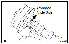
(b) Cover all the paths with vinyl tape except the advanced side path shown in the illustration.
(c) Using an air gun, apply about 150 kPa (1.5 kgf/cm2, 21 psi) of air pressure to the port on the advanced angle side.
CAUTION: Some oil spraying will occur. Contain the spray with a shop rag.
HINT: This operation releases the lock pin for the extreme retarded angle lock.
(d) Under the condition above, check that the camshaft timing gear can be turned by hand to the advanced angle side (counterclockwise), the direction of the arrow in the illustration.
Standard: Must turn
HINT: The camshaft timing gear will turn to the advanced angle side without applying force by hand depending on the force of the air pressure applied. Also, if applying pressure to the oil path is difficult as a result of air leakage from the port, the lock pin may be difficult to be released.
(e) Remove the fringe bolt from the camshaft timing gear.
NOTICE: Be sure not to remove the other 4 bolts.
If planning to reuse the camshaft timing gear assembly, release the straight pin lock first, and then install the gear.
16. INSTALL CAMSHAFT TIMING GEAR ASSY
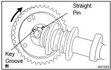
(a) Put the camshaft timing gear and the camshaft (intake) together with the straight pin and key groove.
(b) Turn the camshaft timing gear (as shown in the illustration) while pushing it lightly against the camshaft (intake).
Push further at the position where the pin gets into the groove.
NOTICE: Be sure not to turn the camshaft timing gear to the retarded angle side (to the right direction).
(c) Check that there is no clearance between the gear's fringe and the camshaft (intake).
(d) Tighten the fringe bolt with the camshaft timing gear fixed.
Torque: 54 NVm (551 kgfVcm, 40 ftVlbf)
HINT:
- Apply a light coat of engine oil on the threads and under the head of the bolt.
- Length of sprocket bolt excluding bolt head: 40 mm (1.57 in.)
(e) Check that the camshaft timing gear can move to the retarded angle side (to the right direction) and is locked at the extreme retarded angle.
17. INSTALL CAMSHAFT (INTAKE)
(a) Install the timing chain on the camshaft timing gear, with the painted mark of the link aligned with the timing marks of the camshaft timing sprocket
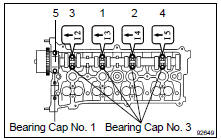
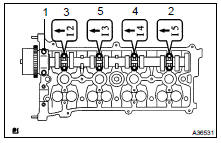
(b) Examine the front marks and numbers of the 5 bearing caps and install them. Then install the 10 bearing cap bolts. Uniformly tighten the bolts in the sequence shown in the illustration.
Torque:
30 NVm (306 kgfVcm, 22 ftVlbf) for bearing cap No. 1
9.0 NVm (92 kgfVcm, 80 in.Vlbf) for bearing cap No. 3
HINT: Apply a light coat of engine oil on the threads and under the heads of the bolts.
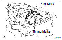
18. INSTALL NO.2 CAMSHAFT (EXHAUST)
(a) Put the camshaft on the cylinder head with the painted mark of the link of chain aligned with the timing mark of the camshaft timing sprocket
(b) Raising the camshaft, temporarily tighten the sprocket bolt.
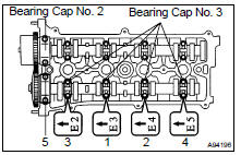
(c) Examine the front marks and numbers of the 5 bearing caps and install them. Then install the 10 bearing cap bolts. Uniformly tighten the bolts in the sequence shown in the illustration.
Torque:
30 NVm (306 kgfVcm, 22 ftVlbf) for bearing cap No. 2
9.0 NVm (92 kgfVcm, 80 in.Vlbf) for bearing cap No. 3
HINT: Apply a light coat of engine oil on the threads and under the heads of the bolts.
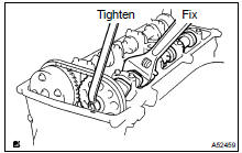
(d) Fix the camshaft with a wrench, and then tighten the sprocket bolt.
Torque: 54 NVm (551 kgfVcm, 40 ftVlbf)
HINT:
- Apply a light coat of engine oil on the threads and under the head of the bolt.
- Length of sprocket bolt excluding bolt head: 25 mm (0.98 in.)
NOTICE: Be careful not to damage the valve lifter.
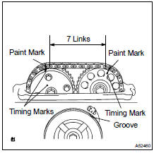
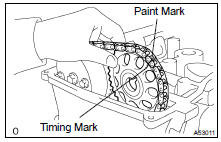
(e) As shown in the illustration, check the paint marks of the timing chain, camshaft timing gear and camshaft timing sprocket and the alignment of the pulley groove with timing mark of the chain cover.
19. INSTALL CHAIN TENSIONER ASSY NO.1 (See page 14-68 )
20. INSTALL CYLINDER HEAD COVER SUB-ASSY (See page 14-41 )
21. CONNECT ENGINE WIRE
22. INSTALL IGNITION COIL ASSY Torque: 9.0 NVm (92 kgfVcm, 80 in.Vlbf)
23. INSTALL SPARK PLUG Torque: 19 NVm (194 kgfVcm, 14 ftVlbf)
24. INSTALL FRONT WHEEL RH
25. CHECK FOR ENGINE OIL LEAKS
 Chain (2AZ-FE)
REPLACEMENT
1. REMOVE HOOD SUB-ASSY
2. REMOVE FRONT WHEEL RH
3. REMOVE ENGINE UNDER COVER NO.1
4. REMOVE FRONT FENDER SPLASH SHIELD FRONT RH
5. REMOVE FRONT FENDER APRON SEAL RH
6. DRAIN ENGINE ...
 Cylinder head gasket (2AZ-FE)
REPLACEMENT
1. WORK FOR PREVENTING GASOLINE FROM SPILLING OUT (See page 11-1 )
2. REMOVE FRONT SUSPENSION BRACE SUB-ASSY UPPER CENTER (W/ FRONT
SUSPENSION
BRACE UPPER CENTER)
3. DRAIN COOLANT (S ...
More about Toyota Highlander:
Transmission valve body ASSY (U241E/U140F)
REPLACEMENT
1. REMOVE ENGINE UNDER COVER NO.1
2. DRAIN AUTOMATIC TRANSAXLE FLUID
(a) Remove the drain plug, gasket and drain ATF.
(b) Install a new gasket and drain plug.
Torque: 49 NVm (500 kgfVcm, 36 ftVlbf)
3. REMOVE AUTOMATIC TRANSAXLE OIL PAN SUB-ASSY
(a) Remove the 18 bolts, oil p ...
