Toyota Highlander Service Manual: Automatic transaxle ASSY (U241E/U140F)
REPLACEMENT
1. REMOVE ENGINE ASSY W/ TRANSAXLE (SEE PAGE 14-24 )
2. REMOVE FRONT DRIVE SHAFT ASSY RH (SEE PAGE 30-21 )
3. REMOVE FRONT DRIVE SHAFT ASSY LH (SEE PAGE 30-21 )
4. REMOVE TRANSVERSE ENGINE ENGINE MOUNTING BRACKET (4WD DRIVE TYPE) (SEE PAGE 31-9 )
5. REMOVE TRANSFER ASSY (4WD DRIVE TYPE) (SEE PAGE 31-9 )
6. REMOVE TRANSMISSION CONTROL CABLE BRACKET NO.2
(a) Remove the bolt and control cable clamp.
7. REMOVE WIRE HARNESS CLAMP
(a) Disconnect the wire harness from the clamp.
(b) Remove the 3 bolts and 2 clamps.
8. SEPARATE WIRE HARNESS
(a) Remove the wire harness.
9. REMOVE STARTER ASSY
(a) Remove the nut and disconnect the starter wire.
(b) Disconnect the connector.
(c) Remove the 2 bolts and starter.
10. SEPARATE CONNECTOR
(a) Disconnect the transmission wire connector.
(b) Disconnect the park/neutral position switch connector.
(c) Disconnect the speed sensor connector.
11. REMOVE TRANSMISSION CONTROL CABLE BRACKET NO.1
(a) Remove the bolt and oil cooler tube clamp.
(b) Remove the 2 bolts and transmission control cable bracket.
12. REMOVE TRANSMISSION OIL FILLER TUBE SUB-ASSY
(a) Remove the ATF level gauge.
(b) Remove the bolt and oil filler tube.
(c) Remove the O-ring from the oil filler tube.
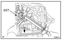
13. REMOVE OIL COOLER INLET TUBE NO.1
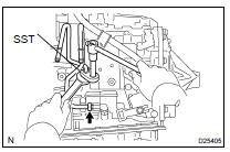
(a) Using SST and spanner, disconnect the oil cooler inlet tube.
SST 09023-12701
14. REMOVE OIL COOLER OUTLET TUBE NO.1
(a) Using SST and spanner, disconnect the oil cooler outlet tube.
SST 09023-12701
15. REMOVE TRANSVERSE ENGINE ENGINE MOUNTING BRACKET
(a) Remove the 2 bolts and engine mounting bracket FR.
16. REMOVE FLYWHEEL HOUSING UNDER COVER
(a) Remove the flywheel housing under cover.
17. REMOVE AUTOMATIC TRANSAXLE ASSY
(a) Turn the crankshaft to gain access and remove the 6 bolts while holding the crankshaft pulley bolt with a wrench.
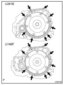
(b) Remove the 9 bolts.
(c) Separate and remove the automatic transaxle.
18. REMOVE TORQUE CONVERTER CLUTCH ASSY
19. INSPECT TORQUE CONVERTER CLUTCH ASSY (SEE PAGE 40-29 )
SST 09350-32014 (09351-32010, 09351-32020)
20. INSTALL TORQUE CONVERTER CLUTCH ASSY
(a) Install the torque converter clutch to the automatic transaxle.
(b) Using calipers, measure dimension A between the transaxle and the end surface of the drive plate.
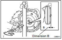
(c) Using calipers and a straight edge, measure the dimension B shown in the illustration and check that B is greater than A measured in (b).
Standard: A + 1 mm or more
21. INSTALL AUTOMATIC TRANSAXLE ASSY
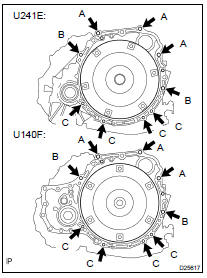
(a) Install the automatic transaxle and 9 bolts to the engine.
Torque: Bolt A: 64 NVm (650 kgfVcm, 47 ftVlbf) Bolt B: 46 NVm (470 kgfVcm, 34 ftVlbf) Bolt C: 37.2 NVm (379 kgfVcm, 27 ftVlbf)
(b) Apply a few drops of adhesive to each 2 threads on the tip of the 6 torque converter clutch mounting bolts.
Adhesive: Part No. 08833-00070 or equivalent
(c) Install the 6 torque converter clutch mounting bolts.
Torque: 41 NVm (420 kgfVcm, 30 ftVlbf)
HINT: First install green colored bolt and then the 5 bolts.
22. INSTALL FLYWHEEL HOUSING UNDER COVER
(a) Install the flywheel housing under cover.
23. INSTALL TRANSVERSE ENGINE ENGINE MOUNTING BRACKET
(a) Install the engine mounting bracket FR and 2 bolts to the automatic transaxle.
Torque: 64 NVm (653 kgfVcm, 47 ftVlbf)
24. INSTALL TRANSMISSION OIL FILLER TUBE SUB-ASSY
(a) Coat a new O-ring with ATF, and install it to the oil filler tube.
(b) Install the oil filler tube and bolt to the automatic transaxle.
Torque: 5.5 NVm (56 kgfVcm, 49 in.Vlbf)
(c) Install the ATF level gauge.
25. INSTALL TRANSMISSION CONTROL CABLE BRACKET NO.1
(a) Install the control cable bracket and 2 bolts.
Torque: 11.8 NVm (122 kgfVcm, 9 ftVlbf)
26. INSTALL OIL COOLER INLET TUBE NO.1
(a) Temporarily install the oil cooler outlet tube.
(b) Temporarily install the oil cooler inlet tube.
(c) Install the oil cooler tube clamp and bolt.
Torque: 5.5 NVm (56 kgfVcm, 49 in.Vlbf)
HINT: Install them so that the oil cooler tube cushion is positioned as illustrated.
(d) Using SST and spanner, tighten the oil cooler inlet tube.
SST 09023-12701
Torque: 34.3 NVm (350 kgfVcm, 25 ftVlbf)
27. INSTALL OIL COOLER OUTLET TUBE NO.1
(a) Using SST and spanner, tighten the oil cooler outlet tube.
SST 09023-12701
Torque: 34.3 NVm (350 kgfVcm, 25 ftVlbf)
28. INSTALL STARTER ASSY
(a) Install the starter and 2 bolts.
Torque: 39 NVm (398 kgfVcm, 29 ftVlbf)
(b) Connect the connecter.
(c) Install the starter wire and nut.
Torque: 9.8 NVm (100 kgfVcm, 87 in.Vlbf)
29. INSTALL WIRE HARNESS
(a) Install the wire harness and bolt.
Torque: 25.5 NVm (260 kgfVcm, 19 ftVlbf)
30. INSTALL WIRE HARNESS CLAMP

(a) Install the 2 clamps and 3 bolts.
Torque: 8.4 NVm (86 kgfVcm, 74 in.Vlbf)
(b) Connect the wire harness to the clamp.
31. INSTALL TRANSMISSION CONTROL CABLE BRACKET NO.2
(a) Install the control cable clamp and bolt.
Torque: 11.8 NVm (122 kgfVcm, 9 ftVlbf)
32. INSTALL TRANSFER ASSY (4WD DRIVE TYPE) (SEE PAGE 31-9 )
33. INSTALL TRANSVERSE ENGINE ENGINE MOUNTING BRACKET (4WD DRIVE TYPE) (SEE PAGE 31-9 )
34. INSTALL FRONT DRIVE SHAFT ASSY LH (SEE PAGE 30-21 )
35. INSTALL FRONT DRIVE SHAFT ASSY RH (SEE PAGE 30-21 )
36. INSTALL ENGINE ASSY W/ TRANSAXLE (SEE PAGE 14-24 )
 Adjustment
1. INSPECT SWITCH ASSY, NEUTRAL START
(a) Apply the parking brake and turn the ignition switch to the ON
position.
(b) Depress the brake pedal and check that the engine starts only when the shift ...
 Automatic transaxle ASSY (U151E/U151F)
COMPONENTS
REPLACEMENT
1. REMOVE ENGINE ASSEMBLY WITH TRANSAXLE (SEE PAGE 14-149 )
2. REMOVE FRONT DRIVE SHAFT ASSY LH (SEE PAGE 30-21 )
SST 09520-01010, 09520-24010 (09520-32040)
3. REMO ...
More about Toyota Highlander:
On-vehicle inspection
1. DOOR LOCK FAIL-SAFE
(a) When a malfunction in the door control switch (manual switch, operation
interlocked with key) has been
detected, door LOCK/UNLOCK operation become disabled.
2. CHECK ELECTRICAL DOOR LOCK OPERATION
(a) Check the basic function.
Check that all doors lock when ...
