Toyota Highlander Service Manual: Stabilizer bar rear (4WD)
REPLACEMENT
HINT: COMPONENTS: See page 27-2 .
1. REMOVE REAR WHEEL
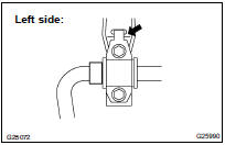
2. REMOVE REAR STABILIZER LINK ASSY LH
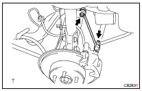
(a) Remove the 2 nuts and stabilizer link.
HINT: If the ball joint turns together with the nut, use a hexagon wrench (5 mm) to hold the stud.
3. REMOVE REAR STABILIZER LINK ASSY RH
HINT: Remove the RH side using the same procedures as for the LH side.
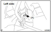
4. INSPECT REAR STABILIZER LINK ASSY LH
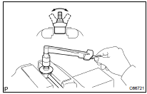
(a) As shown in the illustration, flip the ball joint stud back and forth 5 times.
(b) Using a torque wrench and nut, turn the ball joint continuously at a rate of 3 to 5 seconds per turn and take the torque reading on the 5th turn.
Turning torque: 1.0 N*m (10 kgf*cm, 9 in.*lbf) or less
If the value is not within the specification, replace the rear stabilizer link assy with a new one.
NOTICE:
- Check that neither unusual drag nor rattle occurs during the rotation.
- Check that neither cracks nor grease leakage exists on the dust cover.
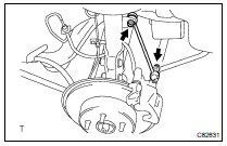
5. REMOVE STABILIZER BAR REAR
(a) Remove the 3 bolts and stabilizer bar.
6. INSTALL STABILIZER BAR REAR
(a) Install the stabilizer bracket.
(b) Install the stabilizer bar with the 3 bolts.
Torque: Bolt A: 54 NVm (550 kgfVcm, 40 ftVlbf) Bolt B: 19 NVm (194 kgfVcm, 14 ftVlbf)
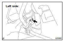
7. INSTALL REAR STABILIZER LINK ASSY LH
(a) Install the stabilizer link with the 2 nuts.
Torque: 39 NVm (400 kgfVcm, 29 ftVlbf)
HINT: If the ball joint turns together with the nut, use a hexagon wrench (5 mm) to hold the stud.
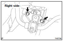
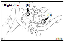
8. INSTALL REAR STABILIZER LINK ASSY RH
HINT: Install the RH side using the same procedures as for the LH side.
9. INSTALL REAR WHEEL Torque: 103 NVm (1,050 kgfVcm, 76 ftVlbf)
10. INSPECT REAR WHEEL ALIGNMENT (SEE PAGE 27-5 )
 Stabilizer bar rear (FF)
REPLACEMENT
HINT:
COMPONENTS: See page 27-2 .
1. REMOVE REAR WHEEL
2. REMOVE REAR STABILIZER LINK ASSY LH
(a) Remove the 2 nuts and stabilizer link.
HINT:
If the ball joint turns together w ...
 Tire & wheel
Wheel and tire system
Inspection
1. INSPECT TIRE
(a) Check the tires for wear and proper inflation pressure.
Cold tire inflation pressure:
(b) Using a dial indicator, check the tire runout.
...
More about Toyota Highlander:
Tires
Replace or rotate tires in accordance with maintenance schedules
and treadwear.
Checking tires
New tread
Treadwear indicator
Worn tread
The location of treadwear indicators
is shown by the "twi" or "ƒ´"
marks, etc., Molded on the sidewall
of each ti ...
